This thread has been locked.

If you have a related question, please click the "Ask a related question" button in the top right corner. The newly created question will be automatically linked to this question.

LP8764-Q1: Inductance value selection

Part Number: LP8764-Q1

Hi TI team,


I would like to check with you for the L inductance value buck 3 of LP8764-Q1.

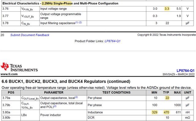
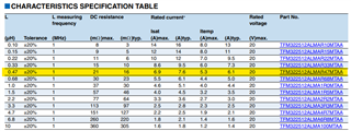
You guys have recommended me typical value of 470pF, but could it be lower for 330nH?


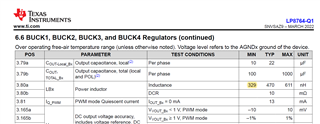
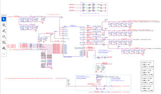
As schematic figure below, I am going to change the value to 330nH L78 from 1uH to handle UVP issue which is caused from fast current transient.

Related issue: e2e.ti.com/.../lp8764-q1-reporting-uv-and-ocp-fault_2

  • Oh! Above typo for typical value of 470pF, should change to 470nH

  • Hi Alex,

    Could you please remind me what are BUCK use cases you are using and switching frequency? Since inductors and capacitors are related to use-case using values outside of ranges will cause strange operation and hence potentially causes additional issues.

    So I would very highly recommend to follow DS with external components.

    Br, Jari

  • Hi Jari,

    Good to hear your feedback.

    The switching frequency is 2.2MHz with buck 3 single phase.

    Datasheet mentioned the typical value is 470nH and minimum 330nH (PN:TFM322512ALMAR33MTAA)

    Since the sink current will go high to 4A, so we need to reduce the inductance lower to support transient load.

    Besides, we adjust the current limit to 6.5A, so this is also need your check for the value setting.

    We are going to change the inductor to TFM322512ALMAR33MTAA (Typ Isat is 9.5A, and Max Isat is 8.6A)

    I think this can fully support our scenario, how about you?

    Thanks,

    Alex

  • Hi Alex,

    That is not right direction. 2.2MHz single/multiphase config is defined to be used with 470nH inductor and inductance can vary between 329-611nH (+-30% from nominal value) under load, temp and other conditions. But typically it has to be 470nH. 

    So strong recommendation is to use 470nH typical inductor. For example TFM322512ALMAR47MTAA. 

    Per table below this inductor Itemp stil meets 6.5Apeak current limit spec. 

    Br, Jari

  • Hi Jari,

    Thanks for your suggestion.

    For this PMIC, do we have any approach to adjust the bandwidth for the compensation through external hardware or address configuration?

    BR,

    Alex

  • Hi Alex,

    There is no way externally adjust compensation network or any of those parameters. Only way is to select appropriate BUCK use-case and go with that. 

     Based on NVM I see 2.2 MHz SP/MP config and schematics are showing quite good amount of caps as well. This is the most aggressive settings available. 

    Br, Jari