This thread has been locked.

If you have a related question, please click the "Ask a related question" button in the top right corner. The newly created question will be automatically linked to this question.

LMG1025-Q1: Generating 1ns pulse for LMG1025 input

Part Number: LMG1025-Q1
Other Parts Discussed in Thread: LMG1210, LMG1020

Hi TI,

I'm considering using LMG1025 to synthesize 1ns pulses for the input of another LMG1025 (which subsequently drives a GaN FET).  Can these LMG1025s be connected together simply by placing a current-limiting resistor between the first LMG1025's output and the next LMG1025's input?

  • Hi Ruth,

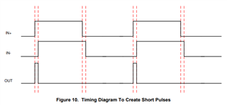
    Yes, you can use the output of one LMG1025-Q1 to input nanosecond pulse into another LMG1025-Q1, which is one of the ways to generate nanosecond pulses described in section 8.2.2.2 in the LMG1025-Q1 datasheet (page 12). That section also describes another simpler way of generating nanosecond pulses using two identical signals: one inputted into IN+ and its delayed version into IN-. I have attached the plot from the datasheet that describes the method below for your convenience:

    Thanks,
    Rubas

  • Thanks! I'm trying to build a half-bridge GaN driver which can operate beyond the 200V limitations of LMG1210, using a pair of isolated LMG1025s.  The differential pulse generation scheme from the LMG1025 datasheet works well for the low side, but I couldn't figure out how to make it work for the complementary pulse on the high side. 

    The scheme from Figure 10 could be used to generate identical pulses at the low side and the high side.  In the low side, feed the pulse to the positive input of the gate driver. And at the high side, feed it to the negative input. My concern was that the edges of these pulses could be fast enough to stress out the inputs of the LMG1025.  On the back of an envelope, it seemed reasonable to just put 100 ohms in series between the pulse-generating LMG1025 and gate-driving LMG1025, and keep the layout as low-inductance as possible.  But since chaining gate drivers together was mentioned in the datasheet, I was curious if there are any more details available about the implementation.

  • Hi Ruth,

    Unfortunately there's not much information about the chaining implementation other than what's in the datasheet. The typical minimum pulse width for the LMG1025-Q1 is 1.25ns with rise/fall times of 650/850ps (1ns and 375/350ps for the LMG1020), so as long as it is within those specs, we can guarantee proper function of the device. You can put a resistor in series, but it would slow the rise/fall time.

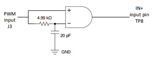
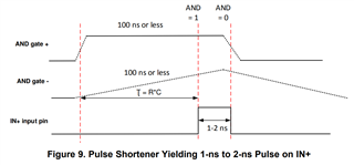
    I'm also not sure if I'm misinterpreting your way of doing differential pulse input, but both the LS and HS LMG1025s need their own differential pulse input. There's also another way of using a pulse shortener to generate nanosecond pulses with only one signal input (this is from the LMG1025 EVM User Guide):


    This FAQ is also helpful for using low-side drivers as high-side drivers: https://e2e.ti.com/support/power-management-group/power-management/f/power-management-forum/1082920/faq-ucc27624-can-i-use-a-low-side-driver-as-a-high-side-driver

    Please let me know if I understood your question, and if not, I'll be glad to continue helping.

    Thanks,
    Rubas