This thread has been locked.

If you have a related question, please click the "Ask a related question" button in the top right corner. The newly created question will be automatically linked to this question.

LMG1210: Abnormal output waveform during startup

Part Number: LMG1210

Dear specialist.

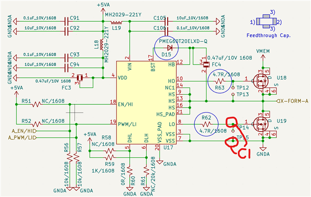
I designed full bridge RF generator using  LMG1210 + EPC2059 as below schematic.

I operate LMG1210 with IIM Mode(Independent Input Mode)

Half bridge Schematic.     Transformer output schematic

Full bridgeHalf bridge-A

Unfortunately, output waveform of high side gate signal is abnormal.

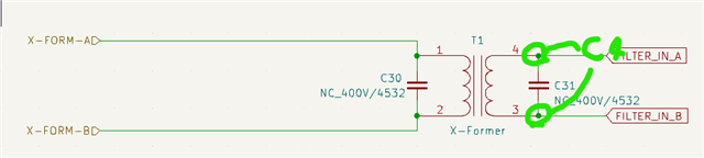
So Transformer's output waveform is not symetric in several wave forms as below picture with circle.

Gate waveform

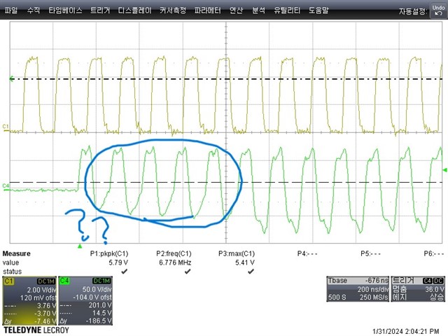
※ C1 : Low side gate waveform.

   C4 : Transformer output waveform.

When rf output is stated,  early several pulse is ignored.  (Several high side pulse is ignored)

But when I contact oscilloscope probe in high side gate or  primary side, wave form is normal.

Please let me know where I check.

Best regards.

그런데 하이사이드 게이트에 오실로스코프 프로브를 접촉시키면 파형이 정상입니다.
  • Hey,

    Thank you for your question regarding the LMG1210.

    1. Is this abnormality only seen during startup? During startup, it may take a few cycles for the bootstrap capacitor to charge completely and provide expected outputs on the high side as this capacitor is needed to source the current for the high-side drive.

    2. What is the need for the feed-through capacitors for the bootstrap capacitor and the bypass capacitor? These two capacitors are used for sourcing current and this is not normally seen here.

    3. Your bootstrap capacitor is also 0.47uF, which is larger than typical here and your bypass capacitor is also 0.47uF. It is recommended that the bypass capacitor be at least 10 times larger than the bootstrap capacitor to help source enough current. We advise that these be ceramic, X7R type capacitors as well. With too large of a bootstrap capacitor at this frequency, it may not charge completely as well as it takes longer to charge on startup which is what you are seeing here. Section 8.2.2.1 Bypass Capacitor discusses this some in the datasheet.

    Let me know your responses to my questions and if you have any further questions.

    Thank you,

    William Moore

  • Hey,

    I apologize on the feedback capacitor note, I see now that we do list feedback capacitors for the bypass and bootstrap capacitor on the EVM for this device and both are 0.47uF so it is acceptable to leave those in place in your design. Also you have the 10uF and 0.1uF as bypass capacitors as well so you are covered there.

    Thank you,

    William Moore

  • Dear William Moore.

    Thanks for your kind advise. 

    1) Abnormal waveform is  always  happened when  startup .

        But I'm worried about that  abnormal pulse wave number is random.

        In some case, 3~4 pulse is not output.  and worst case 7 pulses is not output.

        ※ When I contact Oscilloscope probe in High Side Gate driver or contact HS (in my schematic X-FORM-A or B),   waveform is operate well.

    2) Bootstrap Capacitor Voltage

     -  Before pulse is out, voltages in bootstrap capacitor is always reach  almost 5V. 

    3) Bootstrap Capacitance.

    I tried to change bootstrap capacitor 0.47uf --> 10nF.  But this abnormality is also happened.

    I will show you  normal and abnormal waveform more.

    It takes time  a several days. I will reply to next week again.

    Thanks lot~!

    부트스트랩 커패시터를 0.47uf --> 10nF로 변경하려고 했습니다.
  • Hey,

    So what you are seeing with no HO output on startup is due to the time that it takes for the bootstrap capacitor to charge. The bootstrap capacitor charges when LO is on and HO is off. So, for example, with a period of approximately 150ns, when you see 7 missing pulses, that equals 1.05us of startup time. As shown in the Section 6.6 Switching Characteristics table in the datasheet, the typical start-up time is 16us. So you are well within what is expected at 1.05us.

    To see this, you could monitor HB-HS with a differential probe to see it rise above the UVLO threshold and then begin driving HO.

    The variance you see from 3 to 7 pulses without output is likely do the the status of the bootstrap capacitor prior to startup as well as variances in how fast it charges up. So the amount of pulses you see if related to the charge time of that capacitor.

    Again, this is normal operation and so what is seen is as expected.

    Let me know if you have any further questions.

    Thank you,

    William Moore

  • Dear William Moore.

    Thanks for your good explanation.

    I understand why this happen.