This thread has been locked.

If you have a related question, please click the "Ask a related question" button in the top right corner. The newly created question will be automatically linked to this question.

UCC28730-Q1: UCC28730-Q1 control

Part Number: UCC28730-Q1

Dear Team, 

Customer has been analyzing the UCC28730-Q1 datasheet, and raised some queries regarding the control. Please, can you give us your feedback?


  1. VCCR parameter

Datasheet: “The term VCCR is the product of the demagnetization constant, 0.432, and VCST(max)”


I don’t clearly understand why the RCS formula uses VCCR instead of VCST.


                I thought that I should calculate the Rcs by the maximum current peak of magnetizing inductance of transformer (Ipp) and the Vcst (voltage across resistor). So, using this equation:


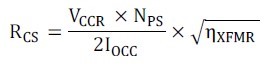
                → Please, can you clarify?


  1. DMAGCC parameter

Datasheet: “DMAGCC is defined as the secondary diode conduction duty cycle during constant current, CC, operation. In the UCC28730-Q1, it is fixed internally at 0.432.”


                → For calculation, I should consider 0.432 as the maximum Duty of demagnetization time. Right?

                So, in voltage mode, it will be always lower.        


thanks

regards, 

Juri          

  • Hi Juri,

    Thank you for the query on UC28730.

    Lets forget about the suare root of efficiency term at the moment.

    Iout = (Ipp/2) x Nps x (tdm/tsw)

    When the controller is at full load where it is at transition between CV and CC mode, the ratio of tdm/tsw approaches close to 0.432. This will be the point for which controller is dsigned.

    Iout = (Vcst_max/2*Rcs) x Nps x 0.432; where Vcst_max =740mV

    Rcs = (0.74x 0.432) x Nps/(2 x Iout)

    Rcs = 0.319 x Nps/(2Iout)

    So Rcs = Vccr x Nps/ (2 x Iout)

    Hope this helps.

    Regards,

    Harish

  • Hi Harish, 

    thanks. This was definitely helpful.  

    Additionally, there are two another questions related to UCC28730-Q1 coming from customer:

    1) Which is its duty resolution?

    2) Is there some strategy to perform a soft start up (HV). Like, adding some delay since it is detected the HV voltage threshold (30V).

    thanks, 

    regards, 

    Juri 

  • Hi Juri,

    Thank you for the reply.

    1. There is no mention of duty resolution in the datasheet. Only minimum on-time is mentioned. It is around 225ns.I understand resolution will have an impact on output voltage regulation and it is more synonymous with digital intensive core, but for analog controllers it is nnot mentioned.

    2. Limiting the startup current on HV pin, increasing Vdd pin capacitor and output capacitor can help to add/ slow down the startup process.

    Regards,

    Harish