This thread has been locked.

If you have a related question, please click the "Ask a related question" button in the top right corner. The newly created question will be automatically linked to this question.

LM4040-N: LM4040BIM3X-3.0/NOPB

Part Number: LM4040-N
Other Parts Discussed in Thread: REF35,

Hi Team,

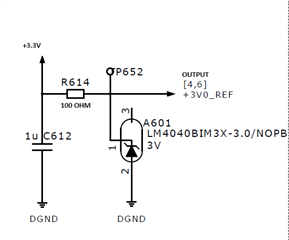
We are using this 3V Shunt voltage reference IC (LM4040BIM3X-3.0/NOPB) in our design.
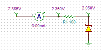
Our input voltage is 3.3V and desired output is 3V 3mA maximum. Using a series resistor of 100ohm.

We have not connected any load at output side of this circuit.

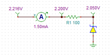
As per design the current flowing through the resistor should be V/R = (3.3 - 3)/100ohm = 3mA,  but we were getting 1.5mA current through series resistor.

How this is possible? as per datasheet the minimum operating current is 65uA.

  • Hello,

    A shunt reference device will always consume excess current provided through the series resistor. The minimum operating current is the minimum needed for the device to regulate the voltage but it will consume excess current if it is available. If a low power solution is needed, the REF35 series reference device has a typical current consumption of 0.65uA. Another solution is to increase the size of the series resistor but make sure that the supply current >= 65uA + ILoad. 

    Thanks,

    Walter

  • Thanks Walter,

    My doubt is, if we are using 100 ohm resistor the current flowing through the resistor should be 3mA. but here we are getting only 1.5mA while placing a ammeter in series with resistor. So where is the remaining 1.5mA. 

  • Are you measuring a constant 3V output from the shunt?

    Thanks,

    Walter

  • yes, we were getting a constant 3V in output side.

  • Hello,

    It should be physically impossible to not have 3mA through the resistor with an exact 3.3V input, 3V output and 100 ohm resistor as (3.3-3)/100 = 3mA. If your input is actually 3.15V then the current will be 1.5mA.

    Can you double check the input voltage, resistor value, and measurement equipment? After placing the ammeter in series with the input resistor, measure the input voltage after the ammeter as it may add an offset to the measurement. 

    I do not have a 3V LM4040-N part available but I tested this circuit with a 2.05V LM4040-N device. The ammeter added a ~35mV drop at 3mA (~11ohms * 3mA) so I also measure the voltage after the ammeter to calculate exactly 3mA through the resistor. (2.35-2.05)/100 = 3mA. 

    Test setup and measurements :

    If I limit the current from the supply to 1.5mA, the input voltage falls to 2.2V.

    Thanks,

    Walter

  • Hi Walter,

    Thanks for the information, We will ensure the instrument setup once more.