This thread has been locked.

If you have a related question, please click the "Ask a related question" button in the top right corner. The newly created question will be automatically linked to this question.

UCC28730-Q1: UCC28730-Q1

Part Number: UCC28730-Q1
Other Parts Discussed in Thread: UCC28730

Hello,

Regarding the controller UCC28730-Q1, I have another 2 concerns:

1. In order to keep the stability in all the operating range, it is indicated the next equation of Cout (Ecuation 22 of datasheet):

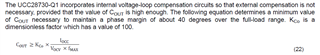
My question is: Is fMAX the maximum indicated at datasheet (83.3kHz), or can be 28kHz (minimum switching frequency of the controller)?

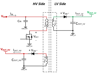
2. In our design, we are using the Auxiliary winding to also supply some loads (150mA).

In this scenario, how it impact on the ecuation that determines the output capacitance? The same ecuation for each rail?

  • Hi Magi,

    Thank you for the query on UCC28730.

    1. Yes, the maximum frequency to which this controller can be programmed is 90Khz. Depending on the choice of primary inductor the max. freuency will be decided. Higher Lm will pusk Fsw lower.

    2. The output capacitance equation still remains same.Take some headroom on Iocc to account for the additional loads.

    Only issue is that if the load on aux winding is higher than output (main) regulation winding, there will be additional load regulation error.

    Regrads,

    Harish

  • Thanks for your feedback.

    Regarding question 2. Considering that in our design we have: Sec-LV and Sec-HV, the minimum capacitance for each rail will be:

    - Cout_LV > Kco * (Iocc_LV / (Vocv_LV * fmax))

    - Cout_HV > Kco * (Iocc_HV / (Vocv_HV * fmax))

    Please, see attached the diagram of our topology. I hope it helps to avoid confusions.

    Thank you!

  • Hi Magi,

    Thank you for clarifying.

    This can be treated as any other multiwinding flyback.

    One simplication you can use to size transformer & current sense resistor, is to calculate the toal power (Vhv x Ihv+Vlv x Ilv) and use equations 12,13,& 14. This total power divided by the voltage (which supports max load current) which would be your LV winding, can provide sufficient margin in choosing the Iocc and hence selecting output capacitors.

    So in short, yes you can use the above equations to size your output capacitors.

    Regards,

    Harish

  • Ok, it is clear the total power simplification. I will use it, for calculation.

    And in the capacitor selection, to ensure the stability, considering:

    - Vocv_LV = 16V

    - Vocv_HV = 16V

    - Iocc_LV = 250mA

    - Iocc_HV = 150mA

     - fsw = 83.3kHz

    The minimum capacitance needed at each secondary will be:

    - Cout_LV > Kco * (Iocc_LV / (Vocv_LV * fmax)) -> 18.75 uF

    - Cout_HV > Kco * (Iocc_HV / (Vocv_HV * fmax)) -> 11.25 uF

    Is this correct?

    Thank you!

    Magí 

  • Hi Magi,

    Yes, these are good inital estimates for the dsign.

    Regards,

    Harish

  • Thank you Harish, it is clear.

    Let me add another topic, how can I set the desired switching frequency of converter?

    I tried to fix the magnetizing inductance and Rcs, according datasheet equations, but in the simulations I obtain less switching frequency than calculated.

    1. Can it depend on the Input voltage (we have a high voltage range: 180V - 500V).

    2. Or it is another topic that impact on Vcl? (I have also calculated Rs1, Rs2 and Dmax)

  • Hi Magi,

    Thank you for the reply.

    1. I would recommend following the datasheet equtions or the excel calculator for calculation of parameters. Calculate Nps based on Dmax, Vin_min and Vout. Using this Nps, calculate Rcs. This in turn is used to calculate Ipp. Use Ipk, desire Fsw & P_out to calculate Lm.

    2. Vcl only determins the region of operation in the control law depending on the oad demand.

    Regards,

    Harish