This thread has been locked.

If you have a related question, please click the "Ask a related question" button in the top right corner. The newly created question will be automatically linked to this question.

LM5152-Q1: Caluclation tool: phase margin and gain margin? compensation circuit calculation value? Efficiency curve?

Part Number: LM5152-Q1

Hi team, 

Could you answer following questions for quickstart calculator for LM5152-Q1?

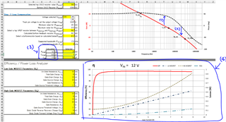
(1) For phase margin, could we refer to the margin shown in lower figure (1)? In this case, phase margin is 70~80 degree, correct?
If no, could you share where we need to refer to? (phase margin of 10Hz is 90 degree instead of 0 degree. Could you share why?)

(2) For gain margin, could we refer to the margin shown in lower figure (2)? In this case, gain margin is 30 degree, correct?

(3) How "calculated" RCOMP, CCOMP, and CHF are calculated?

(4) How efficiency curve is calculated?


Regards,
Ochi

  • Hi Ochi,

    Thanks for reaching out.
    Indeed, the phase margin is determined at point (1). And indeed it seems to be above 60 degrees, which is a good thing. 
    Keep in mind that the stability calculations in the Quickstart Calculators are a pure approximation and don't take parasitic elements of the PCB into account, so the final tuning of the compensation loop should be done in the lab on the actual PCB.

    Now an explanation about why the phase curve starts at 90 degrees. If we take a system with one pole, e.g. Y=1/(1+s). Then the system becomes instable or undefined when s=-1; because the denominator becomes zero. If we now look at what s=-1 means from an amplitude perspective: |s|=1, and from a phase perspective: phase(s) = -180 degrees. So the systems becomes unstable when the phase drops 180 degrees. So there's 180 degrees of phase marginThe curve starts at 90 degrees and not at 180 degrees because there's always a pole present which already drops the phase by 90 degrees.

    Your gain margin would be about 17dB or 18dB. It's determined at point (2) but expressed in decibels. 

    I'd like to refer you to  Switch-mode power converter compensation made easy, to give a foundation of relevant compensation-related topics. It will go into the different rules of thumb and strategies which are used for different topologies and compensation schemes.

    The efficiency curve is calculated by expressing the different losses that occur within a SMPS in a percentage of the total losses. It is important to understand that total losses of let's say a MOSFET are determined by a superposition of the switching losses and the conduction losses.

    Please reach out if you have any other questions.

    Thank you and best regards,
    Bryan