This thread has been locked.

If you have a related question, please click the "Ask a related question" button in the top right corner. The newly created question will be automatically linked to this question.

TPS546D24: TPS546D24 I2C

Part Number: TPS546D24

Hi,

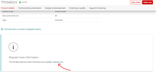
We have new design of board which we using TI TPS546D24 ( not TPS546D24A ).

I have issues of I2C interface.

The first problem is that the I2C address I'm getting in scan does not match the expected I2C address.

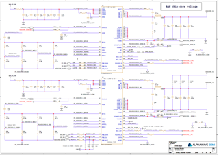
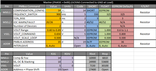
For example we connected ADRSEL pin through 10K OHM resistor to GND and instead of getting address 0x14 we got 0x18.

For example we connected ADRSEL pin through 4.64K OHM resistor to GND and instead of getting address 0x10 we got 0x11.

The only two cases it does match is if I float pin ADRSEL , I'm getting address 0x24 , and when I connect ADRSEL pin to GND, I'm getting back address 0x7F.

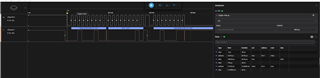
The second problem is if we access to the I2C address as scan result ,the transaction return an error.

We record the I2C transaction and we do see the device answer ACK on the address ,mean that the device is "understanding" that it is being access , but there is no return values.

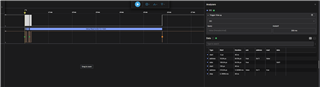
I'm attaching here pictures of the I2C transaction access address 0x11 , you can see that the device does not return values during read , even that it return ACK when we write the address ( the first 8 bits ).

This is the case also with address 0x24 or 0x7F.

We measure pin BP1V5 - it's 1.5V

We measure pin VDD5  - it's 3.9V

Something is not working as expected in the I2C interface of the device.

Thanks,

Avi.

  •  

    TI recommends customers use the TPS546D24A rather than the TPS546D24.

    Based on your descriptions above, your issue is that you are trying to apply the TPS546D24A pin programming options to the TPS546D24, which has a different pin-programming table than the the TPS546D24A.  That is creating a pin-programming error during start-up, which is why VDD is remaining at 3.9V.

    The pin programming error is also why you are seeing a 6ms clock-stretch followed by a NACK on a read attempt.

    10kΩ and 4.64kΩ are not used by the TPS546D24.

    The TPS546D24 uses 32 resistor to ground options and 9 divider options (No divider + 8 resistor dividers)

    The TPS546D24A uses 16 resistor to ground options and 17 divider options (No divider + 16 resistor dividers)

    The reduced number of resistor to ground options used in the TPS546D24A provides additional margin around each option, supporting pin programming over the full temperature range and product life.  The TPS546D24 pin programming is only specified for 0-85C operation during initial power-on with those settings needing to be stored to NVM and having PIN_DETECT_OVERRIDE programmed to 0000h as part of the production test flow.

    For the full TPS546D24 datasheet and design tools, go to the TPS546D24 product folder https://www.ti.com/product/tps546d24 

    Scroll down to "Request More Information" and click "Request Now"

  • Hi Peter,

    I sent request to get the full data sheet of the TPS546D24.

    I still do not understand why in case I put ADRSEL pin floating and access the default address ( 0x24 , EEPROM ) I still got a bus error.

    If VDD is 3.9V it mean that the the device have an error during start-up and that can cause the problem ?

    Thanks,

    Avi.

  •  

    There are a couple of possibilities:

    1) The MSEL2 programming option that has been selected is for a multi-phase configuration and the internal logic is busy attempting to connect to a follower device that it is expecting to be connected to the BCX pins, but isn't.  This causes the I2C port to clock-stretch for 5ms, then NACK when it has not received the requested data to respond to the read request.

    2) The resistor values from the TPS546D24A programming table, which are on the decision boundaries of the Pin Detection windows for the TPS546D24 are producing a logic fault during pin detection and causing it to stall prior to completing, leaving the internal logic in an invalid state and preventing it from responding with data to the read request.

    What resistors / connections do you have for the other 3 pin detection pins?

    MSEL1?

    MSEL2?

    VSEL?

    If you have the options you want, I can help you with the resistor values to use.

    Switching Frequency

    Compensation Option

    Stack Count (Number of Devices)

    Current Limit Option

    Soft-start Time

    Output Voltage

    Address

    SYNC options and phase position (if single phase)

  • Hi Peter,

    I'm still waiting for the TPS546D24 full data sheet.

    If you can send me just pictures of the resistors programming table, it can help me.

    Please see below the values of resistors I set , but as you understand, those values are based by mistake on TPS546D24A data sheet ( I thought that the device are fully compatible , not just pin compatible, and I was wrong ).

    Here is the resistors I places:

    VSEL - 78.7K TOP, 31.6K BOT

    MSEL1 - 44.2K TOP, 17.8K BOT

    MSEL2 - 9.09K TOP, 4.64K BOT

    The options I want:

    Switching Frequency - 900KHz

    Compensation Option -don't care

    Stack Count (Number of Devices)- It is single device

    Current Limit Option - 20 Amp

    Soft-start Time - don't care

    Output Voltage - 0.65V

    Address - 0x23 for device 1 , 0x26 for device 2.

    SYNC options and phase position (if single phase) - don't care

    Thanks,

    Avi.

  • Hi Peter,

    For next assemblies we will place the TPS546D24A as I planned.

    The only reason we assembly the TPS546D24 was because that was the available stock in DigiKey in that point in time.

    I assume that is also the reason that the data sheet of TPS546D24 is not available.

    I notice in other case that you were asked if there is an excel calculator for TPS546D24 , like we have for TPS546D24A.

    Is there such excel file ?

    Thanks,

    Avi.

  •  

    For next assemblies we will place the TPS546D24A as I planned.

    That would be good.  Make sure you use the resistors for the TPS546D24A when you do as the resistor values I provide here wont work for the TPS546D24A.

    There is also a newer version of the TPS546D24A, TPS546D24S.  It uses the same pin-programming resistors as the TPS546D24A and is drop-in compatible with the TPS546D24A, but adds EXT_WRITE_PROTECT and PASSKEY for added protection against unauthorized access of the PMBus commands through a Write Protect feature with more resolution than the standard WRITE_PROTECT command, including the ability to lockout changes to the write permissions to provide a level of protection against malicious actors gaining access to the PMBus while allowing write commands that might be needed by the application.

    The only reason we assembly the TPS546D24 was because that was the available stock in DigiKey in that point in time.

    I assume that is also the reason that the data sheet of TPS546D24 is not available.

    The TPS546D24 is on restricted release, with the datasheet and other tools available through TI's MySecure folder because of the limited range of the Pin programming functions, cold temperature restrictions when operating at input voltages below 5V and high switching frequency, and other general improvements made to the device with the release of the TPS546D24A.

    I notice in other case that you were asked if there is an excel calculator for TPS546D24 , like we have for TPS546D24A.

    Is there such excel file ?

    Yes, there are similar tools for the TPS546D24 in the MySecure folder for the TPS546D24 along with the datasheet.  Unlike the combined design tool for the TPS546D24A, the TPS546D24 design tool for general design and compensation is a separate file from it's pin programming tool.

    Switching Frequency - 900KHz

    Compensation Option -don't care

    Stack Count (Number of Devices)- It is single device

    Current Limit Option - 20 Amp

    Soft-start Time - don't care

    Output Voltage - 0.65V

    Address - 0x23 for device 1 , 0x26 for device 2.

    SYNC options and phase position (if single phase) - don't care

    For device address 0x23 (35d) the resistor programming for the TPS546D24 is:

    For Address 0x26 (38d), the resistors are the same except ASRSEL to AGND changes from 27.4kΩ to 36.5kΩ

    If you can send me just pictures of the resistors programming table, it can help me.

    I will check on your request for access to the MySecure folder for the TPS546D24 as that would be far easier than sharing all of the pin programming tables, text and equations since you would need the full tables, not just the resistor tables.

  • Hi Peter,

    Thanks for the detail answer, I will try the values of the resistor strapping you suggested.

    One more question:

    If the device power on successfully the voltage on pin VDD5  should be 5V ?

    If the voltage on VDD5 is 3.9V it indicate the device failed during power on  sequence ?

    Thanks,

    Avi.

  •  

    The VDD5 voltage is programmable from 3.9V to 5.1V with an initial default of 4.7V.  During power on, VDD5 initially rises to 3.9V and is held there during Power On Reset.  At the end of power on reset, VDD5 changes to it's programmed value, assuming sufficient AVIN voltage.

    A VDD5 voltage of 3.9V generally indicates a failed power-on.  This could be caused by a pin programming error, a compromised NVM memory (typically caused by an AVIN power loss during an NVM STORE operation) or a mismatch between the STACK_CONFIG values and the devices connected via the BCX pins.

  • Hi,

    I do not have all those resistors values.

    I want to be able to talk with the device via I2C.

    I place the pins MSEL1,MSEL2  and VSEL floating , and I short ADRSEL to GND.

    I see that the device get the I2C default address 0x7F , but it still does not reply.

    Is there any default configuration that do not require special values of Rbot and Rtop that I2C will work ?

    Thanks,

    Avi.

  •  

    Try shorting the MSEL2 pin to AGND.

    Floatting the MSEL2 pin is putting the part into 2-phase mode.  When in 2-phase mode, if the BCX pins are also shorted to ground it can cause a logic error that can prevent the PMBus target from responding.

    In addition, make sure you are using the correct read protocol.  The TPS546D24 does not respond to direct read - transaction starting with 7-bit address + Read bit, it requires all transactions to start with the 7-bit address followed by a write bit and then command code.

    Hopefully that will address your issue.

  • Hi Peter,

    You are great support !

    We short MSEL2 to GND and the device response correctly to I2C access.

    Thanks again for the support.

    Avi.