Other Parts Discussed in Thread: LM74700-Q1, LM74900
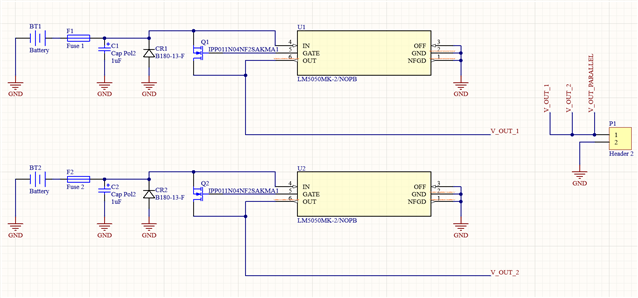
This thread has been locked.
If you have a related question, please click the "Ask a related question" button in the top right corner. The newly created question will be automatically linked to this question.
Hi Charles,
Thanks for reaching out to us!
As far as I understood, your final requirements are:
All three are present in single device from the LM749XX-Q1 family.
LM74900-Q1 data sheet, product information and support | TI.com.
Also, by paralleling the batteries, do you mean to share the current? Ideal diodes do not have active current sharing and hence only of the battery will power the system at a time.
Although ORing is supported for reliable power source. Which means whichever power source is higher in voltage rating, will power the load.
As far as schematic is concerned,
It is recommended to add capacitors at the output as well. 10x CIN should be fine. Also, you might require reverse polarity protection which this device can support with discrete support components, or you can use standalone LM74700-Q1.
LM74700-Q1 data sheet, product information and support | TI.com
Input capacitor used looks polarized. It is better to add ceramic cap as you might see negative voltage on input if reverse battery is connected.
Also, can you help me know the current rating?
Thanks and Regards,
Shiven Dhir
Thanks for your reply Shiven.
For my first iteration, I will be simply trying to switch between the two batteries based on the higher voltage potential to increase run time. Having to share the current between the two is not necessary.
As far as current rating, I have read different experiences with the current draw. During a test, one user in the BlueRobotics forums measured an average of 20A with short spikes in the 60-90A range (while some users reported short spikes in the ~120A range) where the spikes lasted usually no more than a second or two.
With that said, when I am looking at the LM74900, on page 26 of the data sheet, it has output current ranges from 4A nominal and 5A max with an overcurrent limit of 10A.
For the LM74700, on page 16, nominal current is listed as 3A and 5A max. Based off these values, would it be safe to assume these devices would not work under the 20-90A range?
Best regards,
Charles
Hi Charles,
For LM74900:
Values mentioned in the datasheet are for an example design. Overcurrent limit of 10A is just an example which can be programmed using an external resistor.
For currents up to 90A, RILIM value will change.
Hence it can support currents according to the FET chosen.
LM74900 also has a blanking time for which over current is allowed to pass. By which I mean for certain duration of time which current spikes are allowed to pass which is also programmable!
For LM74700:
It is a design example to show calculations to be done to choose supporting components and how to select RdsON of the FET. It can support higher current with the right FET.
For better thermals at higher current, these devices can support parallel operations of FETs as well.
Regards,
Shiven Dhir