


Hi everyone,
i desined an LLC resonant converter and i'm attemting to optimize the gate voltages of the Half-Bridge MOSFETs.
I have these questions:
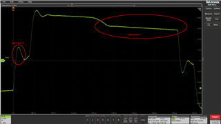
1. Why does the gate voltage decrease during the on time? Is it because the pulse transformer is not working in DC?
2. Why is there a voltage spike during the "dead time"?
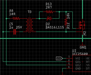
3. Why is the 10kOhm resistor ncessary between Gate and Source? The gate capacitor discharges towards the diode and the inductor winding.
Here is a typical gate voltage acquired with the oscilloscope between Gate and Source.
Here is the schematics of Gate signals.
Thanks,
Best regards.
