This thread has been locked.

If you have a related question, please click the "Ask a related question" button in the top right corner. The newly created question will be automatically linked to this question.

UCC256404: Trouble getting circuit to generate output

Part Number: UCC256404

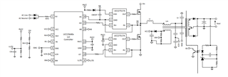
Hello.  I have a design for a high-power converter using the 256404 which is going through the motions of starting up, but doesn't output any significant voltage and keeps rebooting every 1 second.  It is intended to output 30V at 1.2kW.

Input is 400V-DC from my PFC stage, although I have bypassed that at the moment with a bench supply.

I have also provided VCC from bench supply and have put a fixed 1.2V on the BLK input.

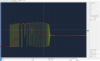
This plot below shows the HO switching voltage (measured at the FET pin) in yellow.
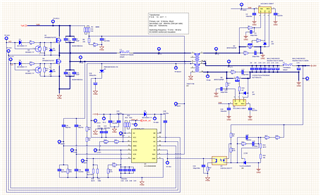
The red trace shows the voltage at the output of the transformer (input of resonance capacitors - TP-B1 on my schematic)

I don't know whether this is a normal waveform to expect, or whether something isn't right.  I'm hoping somebody can point me in the right direction and if I can make more measurements to help diagnose.

Any pointers as to what to look for would be appreciated.

  • We will review it and get back to you.

    Thanks.

  • Hi Ben,

    Could you share the design calculator with your power stage values? Did you try to simulate with the power stage with 40x controller to make sure you put the right passives around the controller.

    Regards

    Manikanta P

  • 3ph rectification maths- LLC only 2.xlsx

    Hopefully this link will work to my Design Calculator.

    Thanks, Ben

  • Did you try to simulate with the power stage with 40x controller to make sure you put the right passives around the controller.

    Hi Manikanta - I'm not sure what you mean by this - what is a 40x controller?  I have posted a link to my design calculator below.

  • Hi Ben,

    I meant UCC256404 controller. Could you try to simulate your power system using the model given here.

    Also, Could you let me know what's the value of capacitance at the LL/SS pin? It's value is not clear in the schematic.

    Regards

    Manikanta P

  • what's the value of capacitance at the LL/SS pin?

    It's 400nF.  The four caps are the same value.

    I'm looking at that simulator, now and will let you know how I get on.

  • Hi Ben,

    Could you try putting 1uF cap at LL/SS pin. That should increase the switching frequency during startup.

    Regards

    Manikanta P

  • Hello - I've been having a bit of success with this design, but also some ongoing problems.  I found a number of manufacturing issues which were preventing it from powering up successfully, and I think I have now eradicated all of those.

    I also completely re-worked the values of the components to run at 100V in and 6V out, because at 400V to 30V it was just instantly blowing both the UCC256404 and the input FETs as soon as power was applied.  Incidentally my transformer turns ratio at 8:1 is not right (for 400V to 30V), I need it to be more like 11:2, hence the change in input:output voltage ratios for testing while I have a new transformer wound.

    At 100V in, 6V out, I have it running quite nicely, but I can only run at about 50W as the output rectifiers are getting very hot - I presume because they are not saturating properly.
    As soon as I remap it for 200V in, 12V out - I apply power and it instantly fries the UCC and the input FETs.  It's getting quite expensive now as I've gone through about 80 FETs and 20 UCC chips.

    I don't know whether it's the FETs bringing the UCC down or vice-versa, but any advice or suggestions would be welcomed.
    Partly to isolate them from each other, I'm considering using an external gate driver to power the FETs, such as the IR2127, but would the turn-on/off propagation delay of these play havoc with the dead-time switching of the UCC?

    Thanks in advance.

  • Hi Ben,

    Here is the way to connect external gate drivers to the UCC25640x:

    Regards

    Manikanta P