This thread has been locked.

If you have a related question, please click the "Ask a related question" button in the top right corner. The newly created question will be automatically linked to this question.

UCC28070: UCC28070 Loss of Gate Pulse

Part Number: UCC28070

Dear TI's support team,

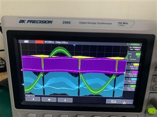
"I have an issue when using the UCC 28070 IC. I am running with a 55VAC input and a 100VDC output to test the features before increasing to 220VAC - 400VDC. However, when I check the pulse, one of the two channels do not have any pulse (I measure at the IC pin). Can you provide me with a solution? Thank you."

  • Hello Manh, 

    If you refer to the Functional Block Diagram in the UCC28070 datasheet, at the bottom, you can see all the internal signals that affect the gate-driver outputs. 

    Essentially, the gate-drive is OFF (output low) whenever the "S" input (Set) of the flip-flop is high.  Lack of pulses means that S is continuously high.
    One of the two S inputs can be continuously high under these conditions: 
    1.  IpeakA or IpeakB is high due to CSA or CSB voltage > PKLMT voltage.
    2.  CAOA or CAOB is shorted to GND and lower than the valley of the PWM sawtooth.
    Please check for either of these conditions and clear the problem.

    Note: OffA and OffB are narrow pulses and are never high continuously.  Fault can be high continuously, but shuts off both gate-drives simultaneously, which is not your symptom. 

    One other possibility for loss of GDx pulses occurs at no-load condition, where VAO voltage is at the 1V threshold for IMO current.
    When IMO is near zero, Vimo is also near zero and either of the CAOx outputs may be slightly below its respective PWM ramp sawtooth valley due to finite offsets. 
    This is similar to CAOx being shorted to GND, but it does not have to be shorted.  Adding a slight load on the output should raise VAO enough to eliminate this condition, and both channels should switch. 

    Regards,
    Ulrich   

  • Thank you so much, Ulrich.

    You are correct, one of the CAOx pins was shorted to GND because Rzc and Cpc were swapped. It's working now. But I encountered another issue, when the input voltage crosses zero point, a large current spike occurs. I've checked the duty cycle and the measured current at CAOx and CSx respectively, and they seem fine. Can you help me figure out the reason?

  • Hello Manh, 

    I'm glad you found the error and got your design running. 

    The current spike that you describe is not unusual, and there is a solution for it.

    This spike happens as the input voltage rises from a zero-crossing, and sometimes there is even a similar spike as the voltage falls into the zero crossing.
    This happens when the CSx signal is lower than the IMO reference voltage and the current amplifier(s) increase their output voltage because the error of the current-sense signal to the reference is higher.  At very low input voltages, the di/dt through the boost inductor may be so low that the average current cannot match what the IMO requires (to match the voltage sine).

    The CAOx error output may be so high that it reaches the internal saturation level of the amplifier drive and clamps around 5V. This drives the GDx duty cycle to the maximum.  As the input voltage rises further, the V/L can drive a faster di/dt and the input current begins to rise quickly.  Because the CAOx outputs had been in saturation, there is a delay for them to come out of saturation.  This delay keeps the duty cycle high when it should be cutting down to limit the rise of current.  Instead, input rises into a spike and comes down to normal sine shape after the CAOx are able to come out of saturation and return to their proper error level. 

    The solution is to make the CAx signals just a little higher than the IMO signal at the zero-crossing to ensure that the CAOx outputs are not drive up into saturation.  This is done by adding a small offset voltage tot the CSx inputs preventing them from going all the way down to 0V. 
    Section 7.2.2.8 of the UCC28070A datasheet (page 40) (https://www.ti.com/lit/gpn/UCC28070A  ) describes how to design this offset.
    A small ramp may also be added.  Or only the ramp and not the offset.  Although the datasheet doesn't say so, these two techniques are independent of each other.  Also, the suggested starting points of 120mV offset and 10% ramp are just suggestions.  The offset and/or ramp can be made smaller or larger as needed for any particular design case. 

    Ideally, they are made as small as possible to mitigate the spike issue without adding significant distortion to light load current shape.
    Adjusting the amount of offset or ramp is a trial and error process, preferably done after all other more important debug is finished.  
    (The same goes for dithering, by the way.  Keep dithering disabled until the system works normally as expected, then enable the dithering and adjust it for optimal EMI improvement.  Debugging with switching waveforms buzzing around from dithering is more difficult.)

    Regards,
    Ulrich

  • Dear Ulrich,

    Thank you for the detailed response!

    Regarding the OFFSET issue at CSx pin, I have read the application note of UCC28070, however, the problem I am having occurs at heavy loads (in that document it says to add offset to solve the problem at light loads). So, I think the problem is not like you described.

    I have measured the GS waveform and the DS through the MOSFET and realized that during the Zero-Crossing, the GS waveform is present, however, the MOSFET is not turned off, causing a sudden increase in current (First 3 pictures). Yellow is Vgs, Purple is Vds, Blue is Ids, and Green is Input current. I think this phenomenon may be caused by the leakage inductance of the Current Transformer. What do you think? And in the last figure (Yellow: Voltage at CSx pin), although there is a spike in the current through the valve, there is no corresponding voltage component at the CSx pin. Therefore, the IC understands that the current is normal and does not adjust a control signal to drive the current to follow the sine waveform of the input voltage. What do you think about this issue? Please give me some advice.

  • Hello Manh, 

    I think it is possible that the current transformers (CTs) are not getting fully reset and loss of signal at CSx near the zero-crossing indicates saturation of the CT.  This can happen even with very current because the CT output diode still has a significant forward voltage drop at mA of current and the duty cycle is normally at maximum leaving very little time to reset.

    I suggest to focus on the zero-crossing, not the entire half-cycle.  With a current probe, compare the actual inductor current or drain current with the CSx voltage and verify that (Vcsx/Rsense)*Nct = Ids during the on-time.  If the equivalent CSx signal is lower than Ids, then I suspect the magnetizing inductance of the CT is diverting most of the sense current from Rsense.  The controller receives the wrong information about how much current there is in the inductor compared to IMO and drives the duty cycle to maximum.  This allows real current to build up in the inductor even though the controller cannot "see" it. 

    To ensure that the CT always resets after each switching cycle, its reset voltage (during the MOSFET off time) should be high enough so that the off-time volt-second product = the on-time volt-second product across the CT winding. If this is not equal, the do what is necessary to either increase the reset voltage or increase the reset time (or both).  Higher voltage can be obtained with a high value reset-resistance or zener.  (The rectifying diode will need to be rated for this reset voltage.)  Longer time can be obtained by reducing Dmax at the DMAX pin.   

    In your 2nd waveform above, you can see that the purple (Ch2) drain voltage does not reach Vout at turn off edges.  It cannot rise high because the available drain current from the inductor is so low that it is unable to charge Coss of your MOSFETs.  Also, the on-time is so long that the MOSFET drain can barely rise before the FET is turned on again in the next switching cycle.  Make sure your MOSFETs are not oversized for this application.  

    First priority is to ensure that the CTs will always be able to reset. 
    Second, cut back on DMAX a little bit.
    Third, consider to add an offset and/or ramp on CSx anyway, for a little insurance against DMAX tolerance variations.  Although this technique is suggested for light load, its principle can also be effective at any load, to help reduce on-time if the reset voltage cannot be increased sufficiently due to other limitations. 

    Regards,
    Ulrich 

  • Dear Ulrich,

    I will check three points according to your advice. I will respond to you as soon as possible. Thank you!

  • Dear Ulrich,

    I have the good news that my problem is solved. When the Magnetizing inductance of CTs is increased, the voltage at ISENSE pins and the current through Ids are almost the same. My input current is so "sine" and the spike current at Zero-crossing point is not appeared. 

    Thank you so much!