Other Parts Discussed in Thread: LM74700-Q1
Hello.
Could you please tell us whether LM74700-EP can drive 6 mos tubes? Now we need a current of 10~15V and 120A, and we plan to use a single LM74700-EP to drive 6 mos tubes? What are the precautions?
This thread has been locked.
If you have a related question, please click the "Ask a related question" button in the top right corner. The newly created question will be automatically linked to this question.
Hello.
Could you please tell us whether LM74700-EP can drive 6 mos tubes? Now we need a current of 10~15V and 120A, and we plan to use a single LM74700-EP to drive 6 mos tubes? What are the precautions?
Hi Xujunfeng,
Thanks for reaching out to us!
First, FET turn on and off time will be increased.
Considering the constant Gate source current and sink current of an Ideal Diode controller. As the number of FETs in parallel increases the turn ON and turn OFF time of the FETs increases due to increase in total gate capacitance.
Approximate calculation can be done as shown:
For Turn ON time calculation, Ton = (Total Ciss) x 5V / peak source current
For Turn OFF time calculation, Toff = (Total Ciss) x 5V / peak sink current
N x FETs will have a total Ciss of N x Ciss (individual)
As an example, Let us consider DMTH43M8LFG as the FET and LM74700-Q1 as the FET controller.
DMTH43M8LFG

LM74700-Q1

4x DMTH43M8LFG FETs have a total Ciss of 4 x 2.798 nF = 11.2 nF
So, the Ton time = (11.2nF) x 5V / 11mA = 5.09 us
and Toff = (11.2nF ) x 5V / 2.3A= 24.3 ns
Similarly, For controllers with back-to-back FET driving capability, same implies to FETs controlled by HGATE also. HGATEs have low charging current on purpose to control the inrush current. By paralleling the FETs turn on time will increase further. Also, it is recommended to use a resistor in series with each FET gate of around 5-10ohms to dampen the oscillations (if any) due to FET parasitic.
Looking at the calculations, decisions can be made on 2 levels to get optimal turn on and turn off time.
1. Effective Ciss of FETs
2. FET controller.
Second, AC super imposed rectification performance.
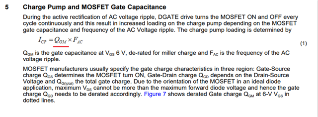
The maximum AC super imposed signal that an Ideal Diode can rectify depends on then FET used and the charge pump current strength. For more understanding on this please refer to the Application Report.
Here, Qgm will increase proportional to the increase in number of FETs and hence maximum frequency that can be rectified will decrease.

As an example,
LM74700-Q1 with 1xDMTH43M8LFG can rectify up to 25KHz whereas with 4x DMTH43M8LFG FETs can rectify only up to 6KHz.
Thirdly, as effective Ciss has increased, charge pump capacitor also has to be scaled accordingly.

Regards,
Shiven Dhir
Thank you for your answer.
Then for our DC10V~15V input, the maximum 120A current, anti-reverse design, can we use 1 LM74700-EP to drive 6 MOSFETs
I can't see the actual impact of the increase in clearance time. And the decrease in the Rectificatio frequency doesn't seem to have any effect on my DC.
Hi Xujunfeng,
Turn on time has an impact on the MOSFET, as till the gate turns on, body diode will be conducting and might get damaged.
Other than that you just need to scale charge pump cap, and the rest is fine.
Regards,
Shiven Dhir
Hi Xujunfeng,
As far as delays are considered, there will be extra delay as mentioned below according to Vcap used.

So, total delay will be T(drv_EN)+Ton_time(as shown in previous messages)
Close time should not matter as it is still very fast, for opening time, it is better to turn on full load once the FET is ON since power dissipation per FET will be very high.
(0.7*current per FET)
You will have to calculate according to your system if it is feasible to turn on full load for body diode.
Regards,
Shiven Dhir
Hello.
With 10V~15V input, 100A maximum load current, 120 OCP。
Please check the schematic
Hi Xujunfeng,
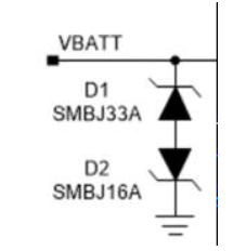
Since you are using 40V rated FETs and if you expect positive transients, we would recommend using 2 unidirectional TVS in back-to-back configuration as shown below.
For more understanding on TVS selection while using 40V rated FETs, please refer to section ‘10.2 TVS Selection for 12-V Battery Systems’ of LM74810-Q1 Datasheet

Other than that, the schematic looks fine.
Regards,
Shiven Dhir
H Xujunfeng,
I didn't notice its a bidirectional TVS.
Yes, should be fine.
Regards,
Shiven Dhir