This thread has been locked.

If you have a related question, please click the "Ask a related question" button in the top right corner. The newly created question will be automatically linked to this question.

LM5164-Q1: Switching frequency does not match with the calculated one and is not fixed over line and load range

Part Number: LM5164-Q1

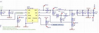
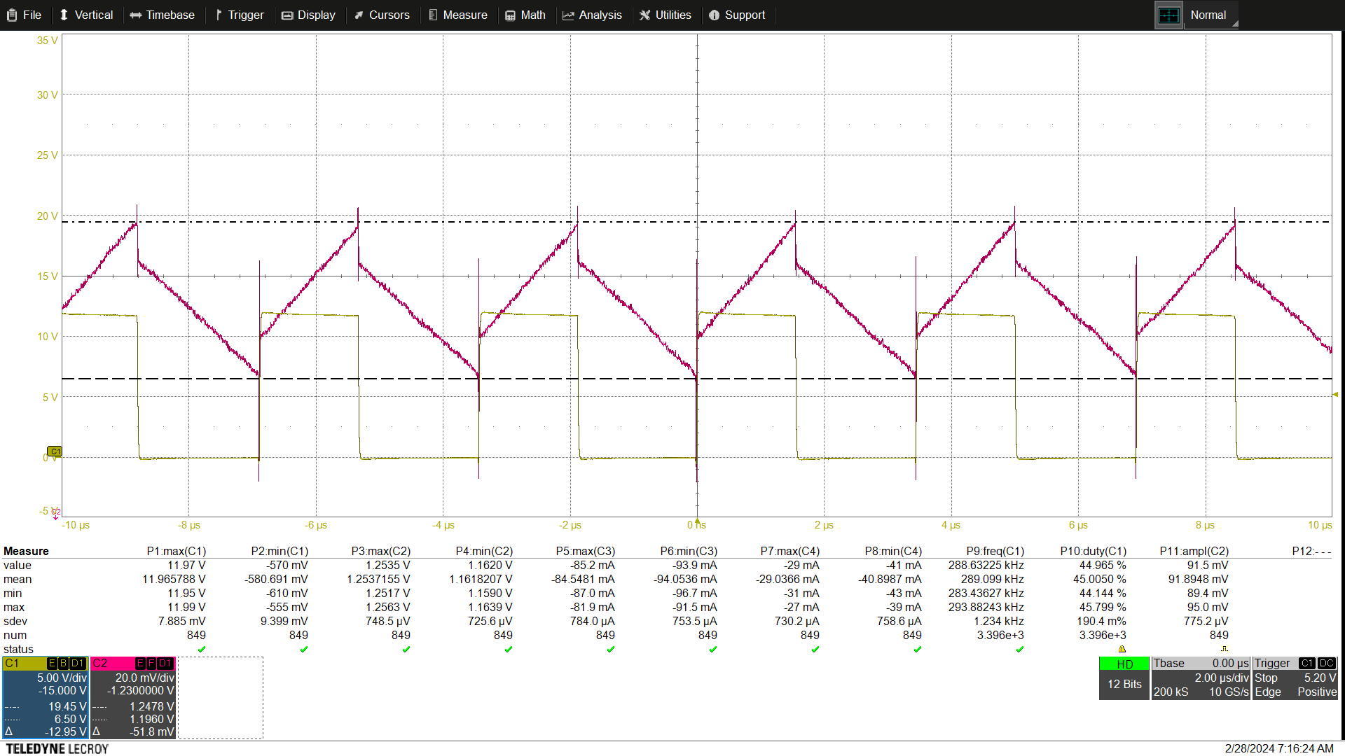
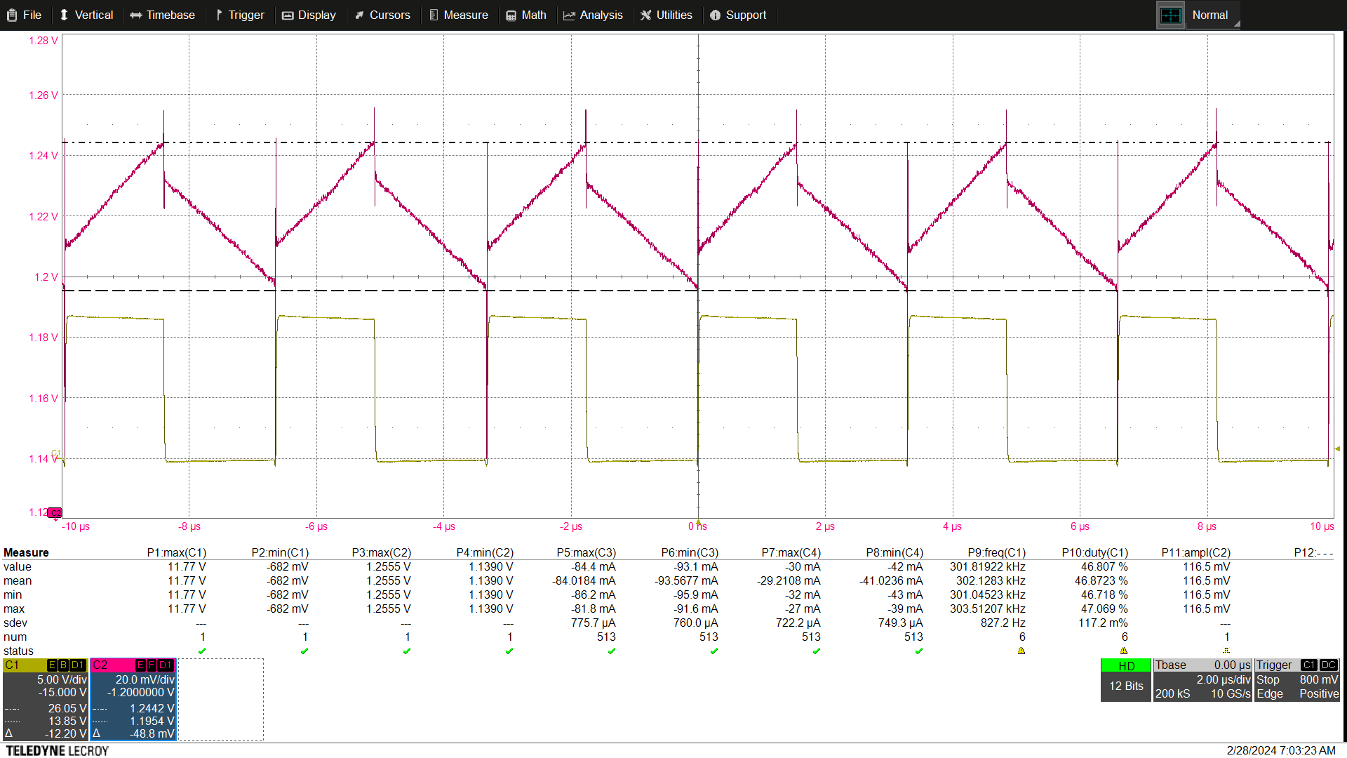
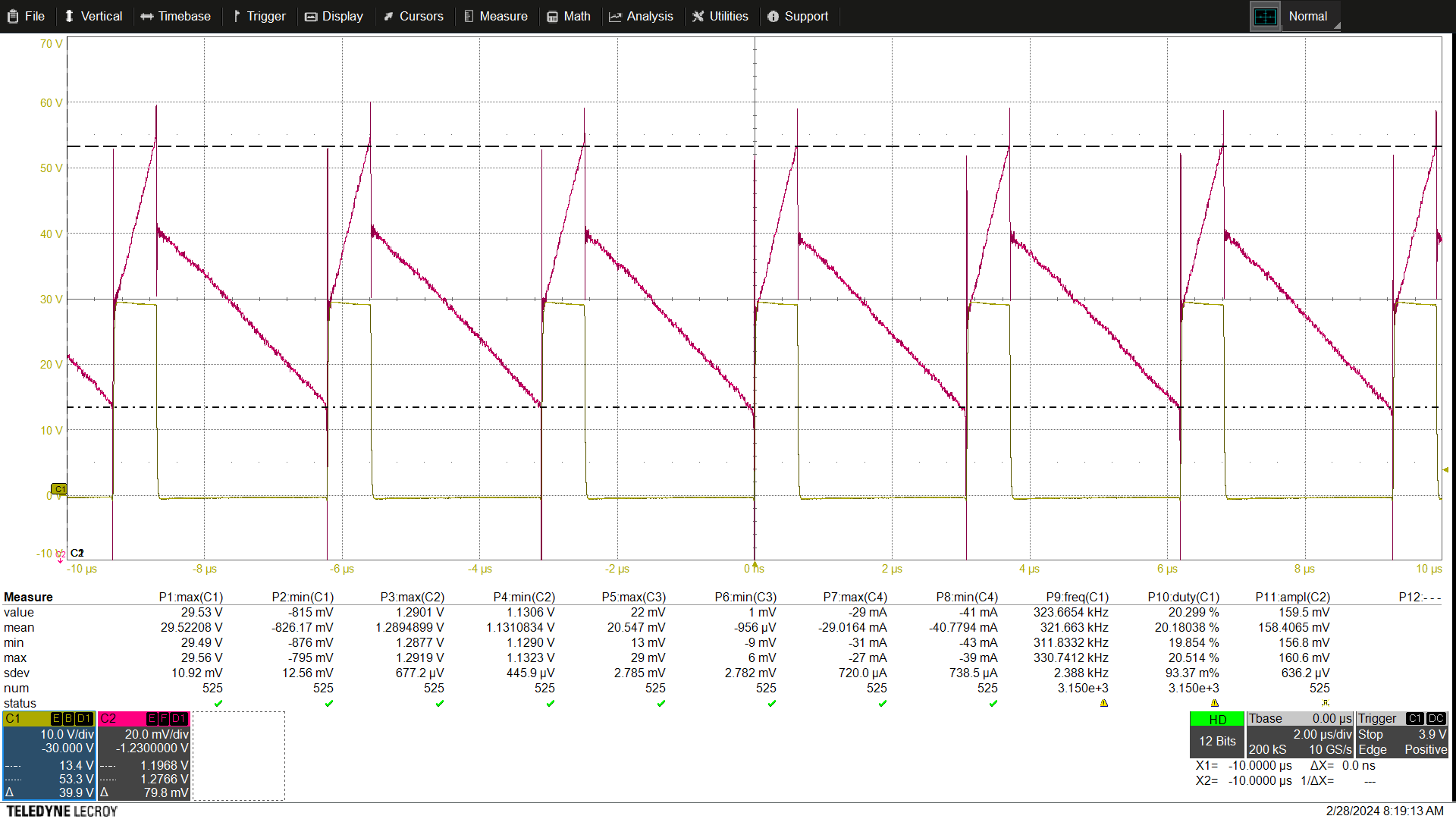
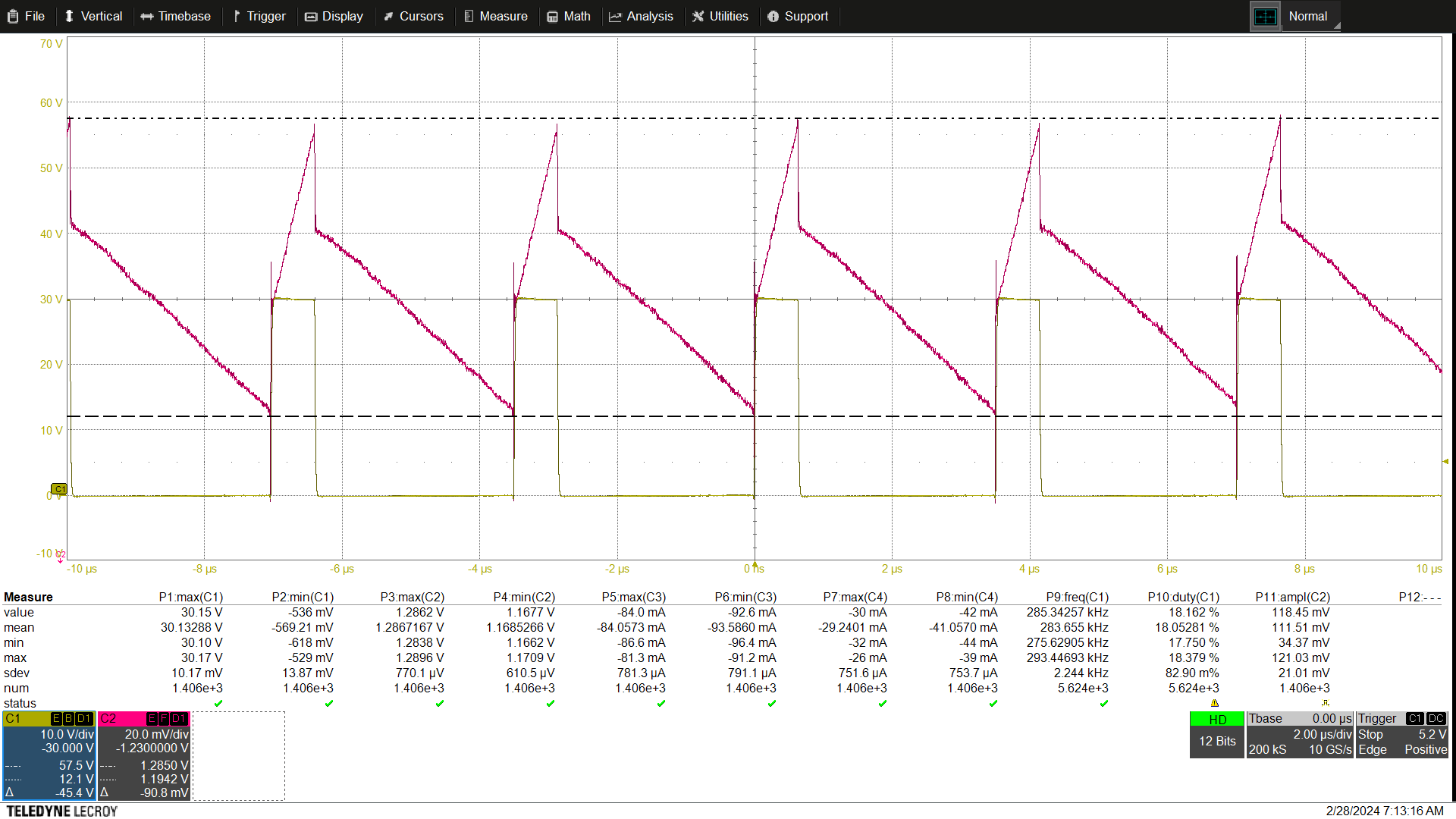
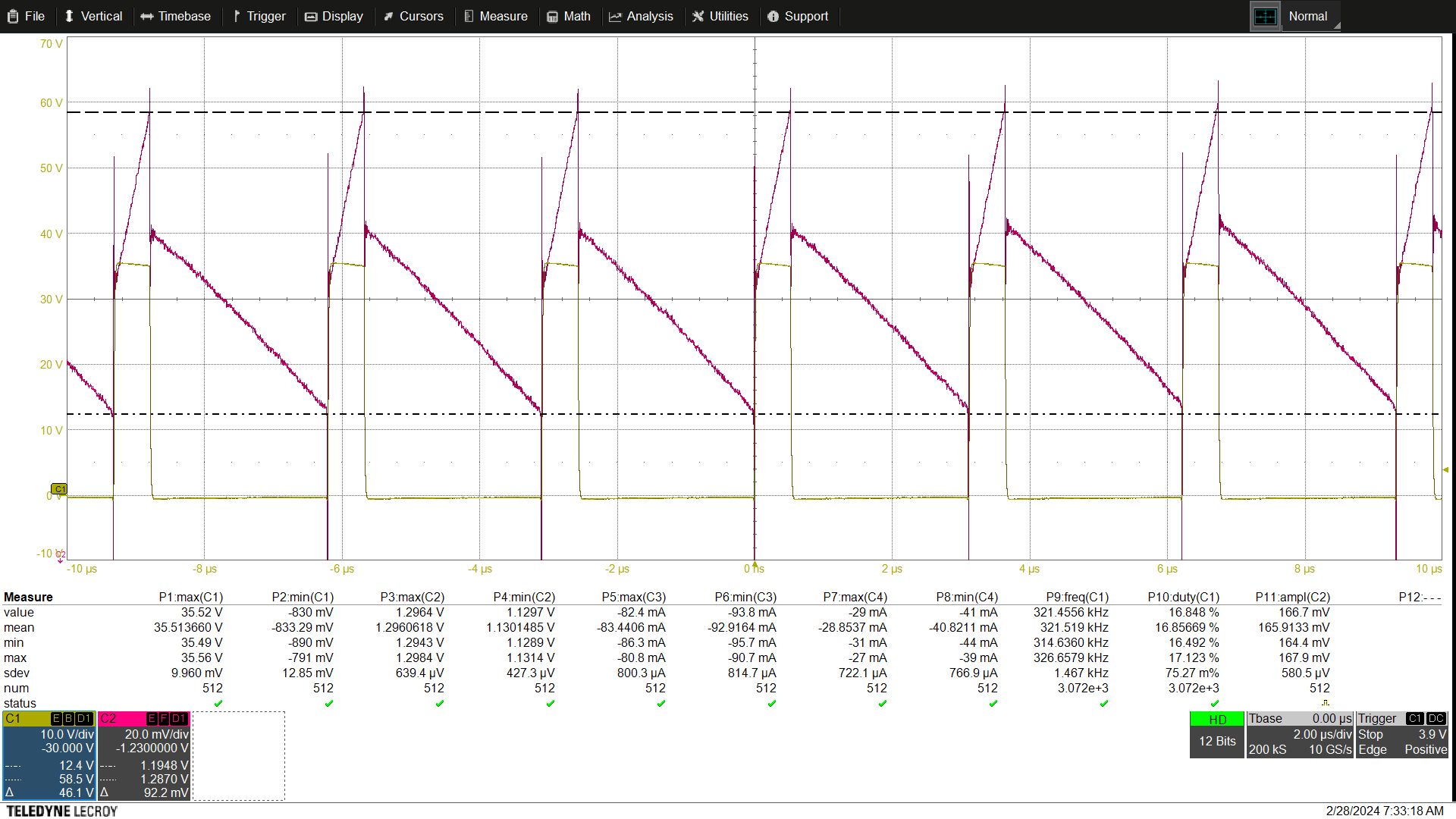
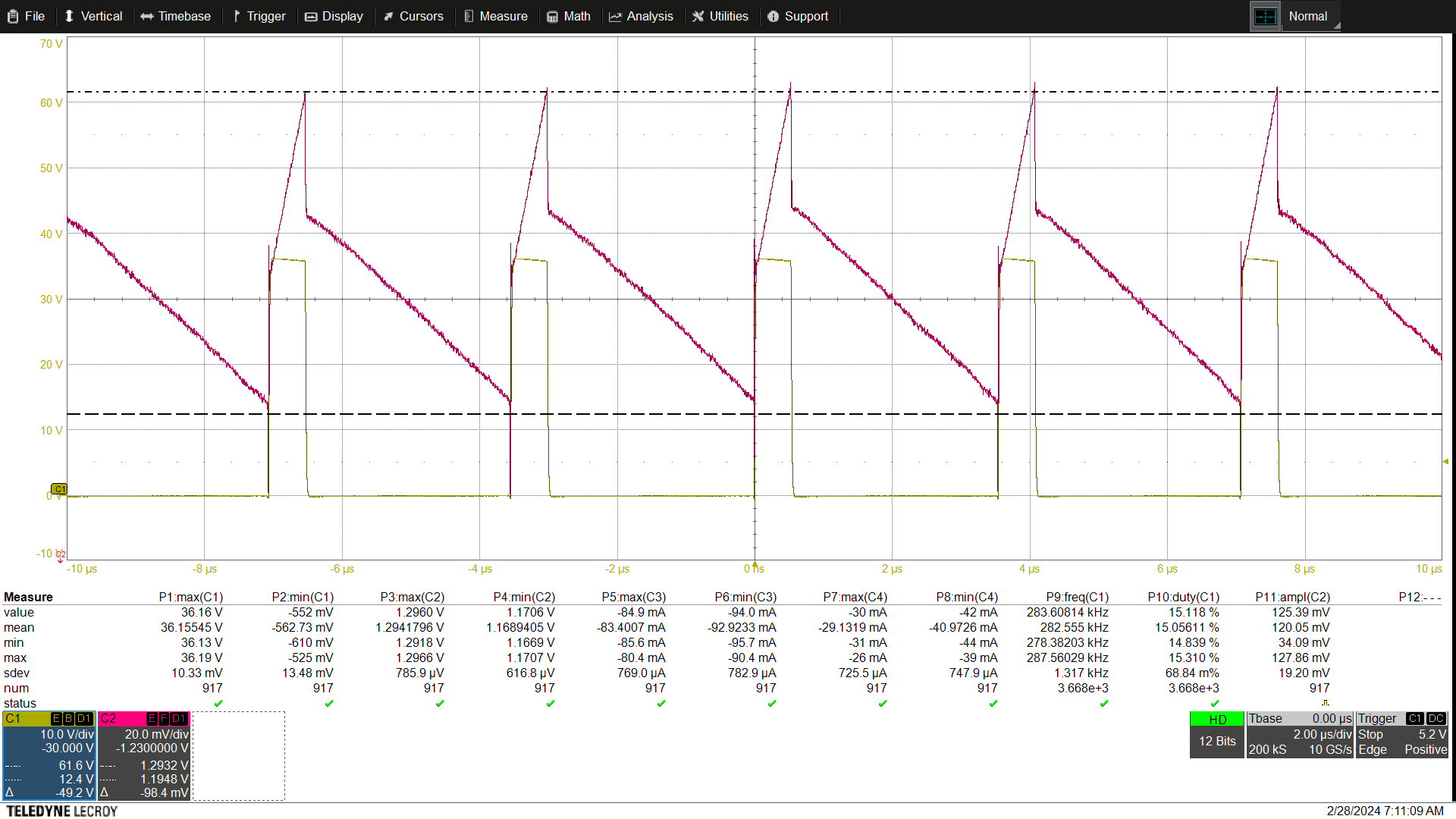
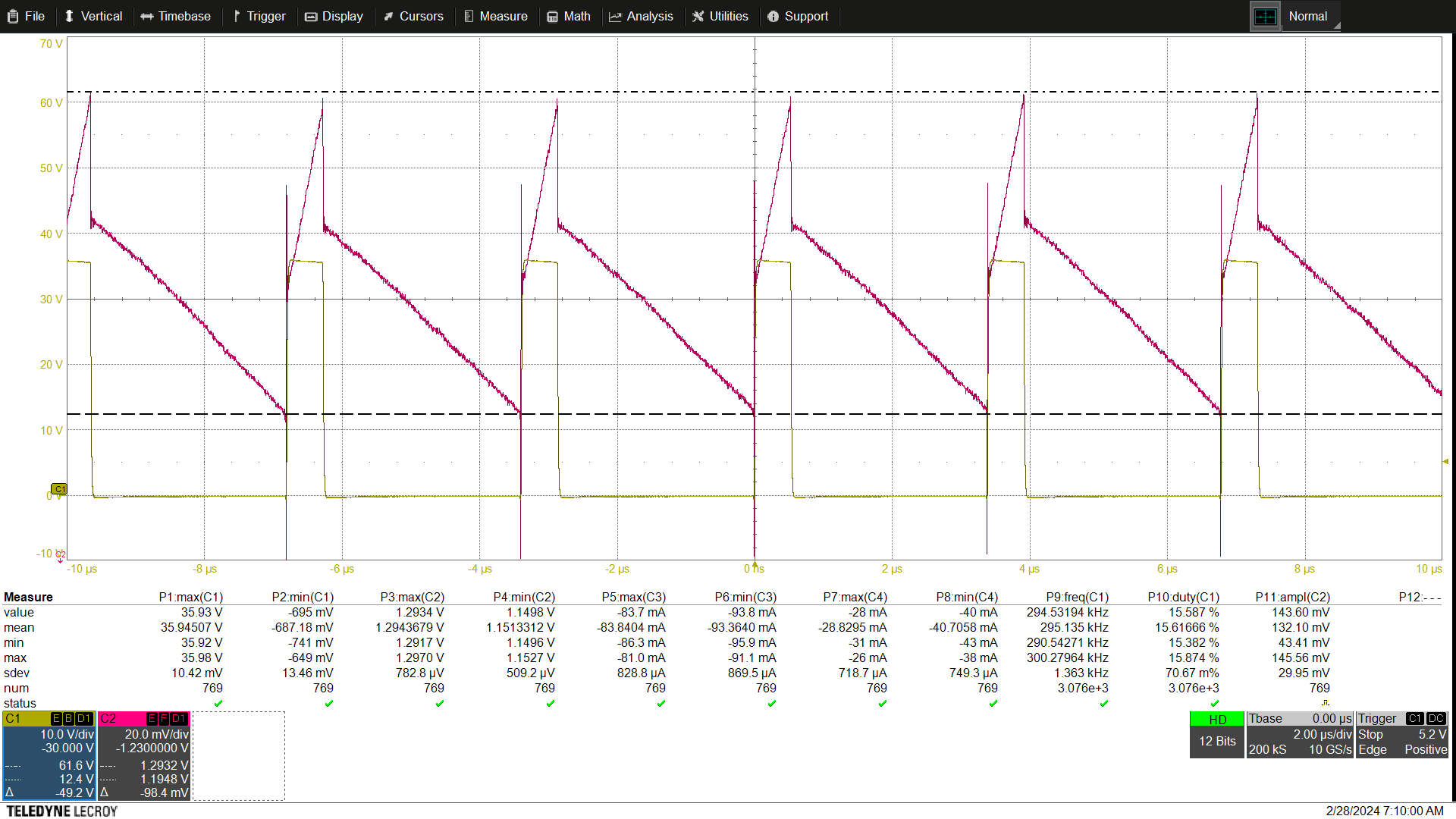
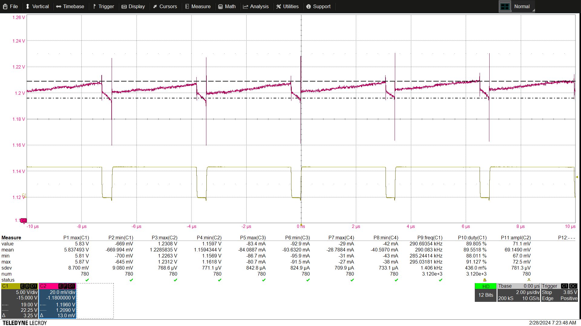
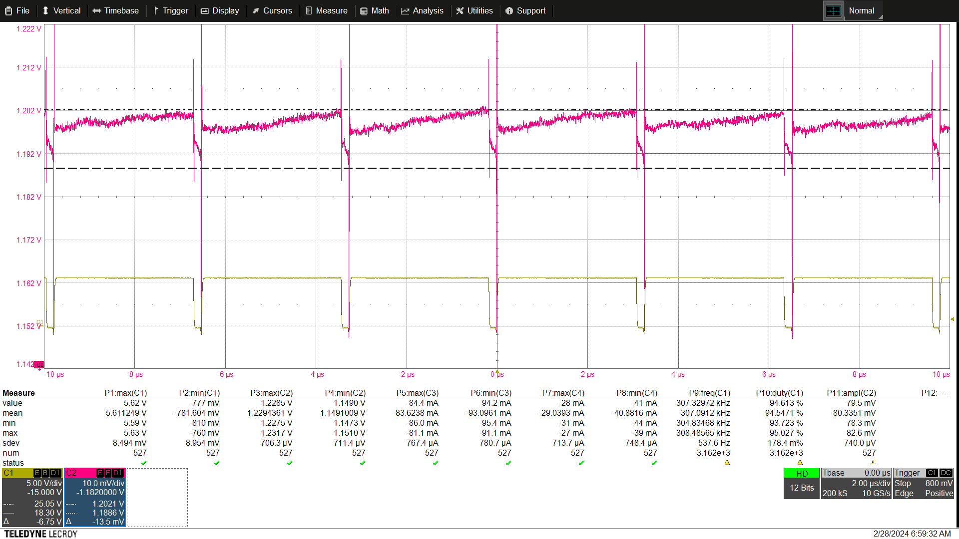
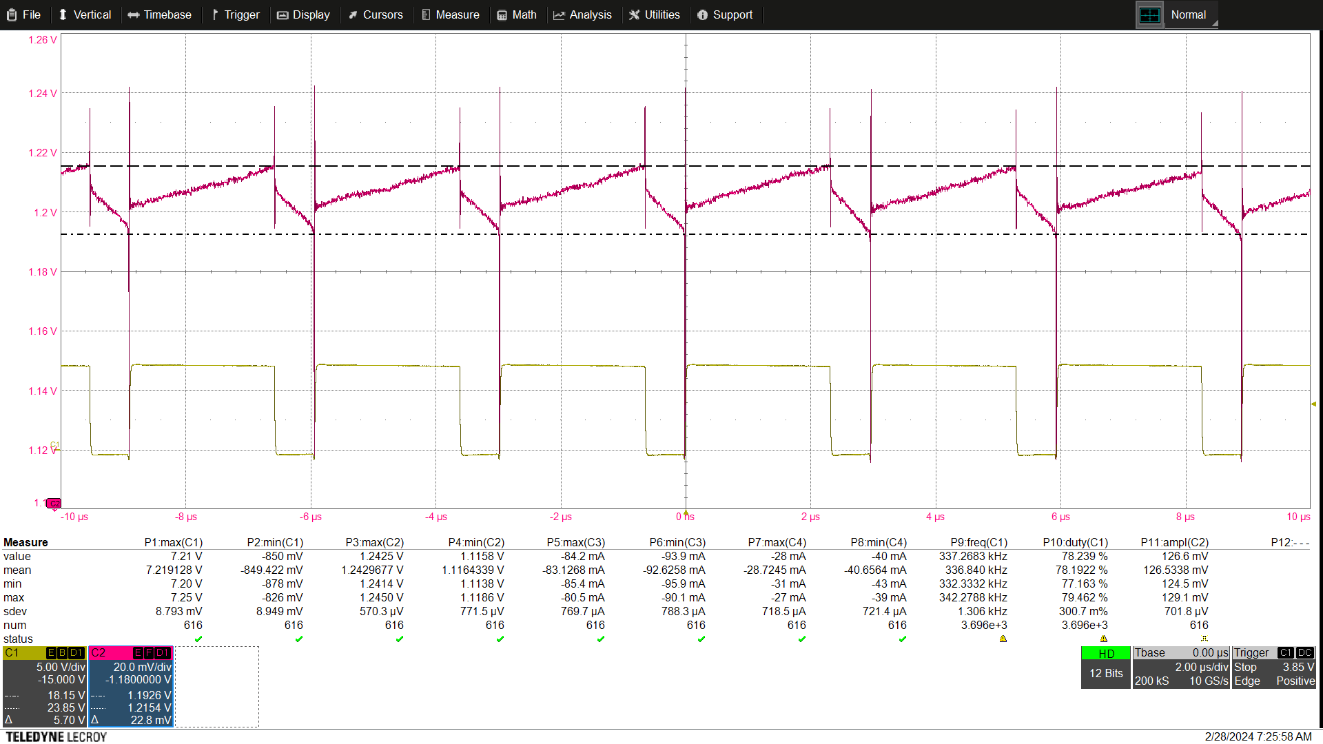
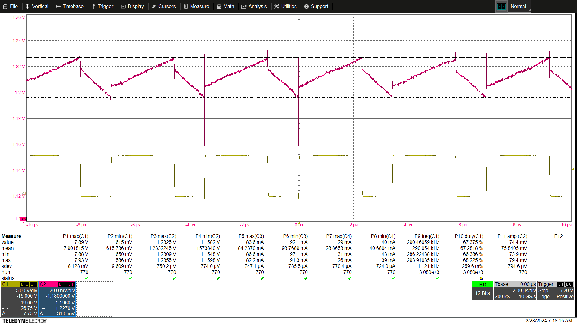
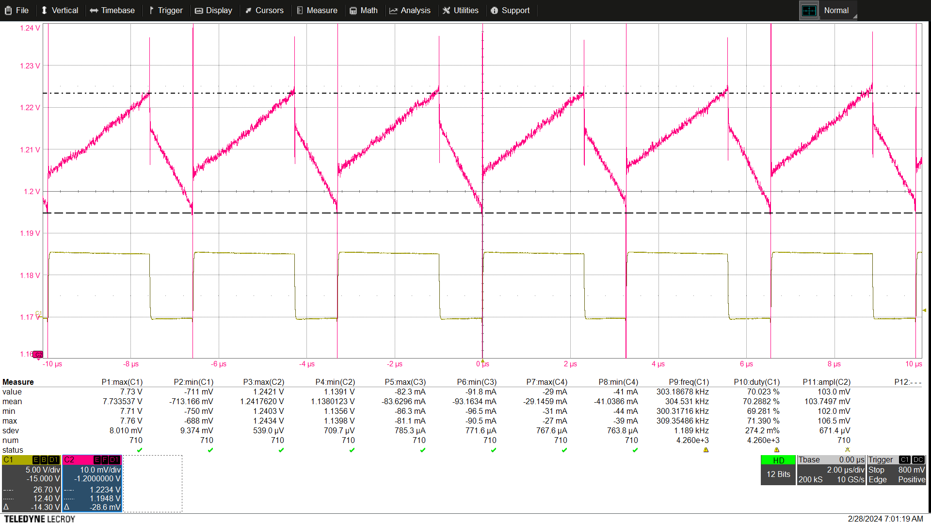
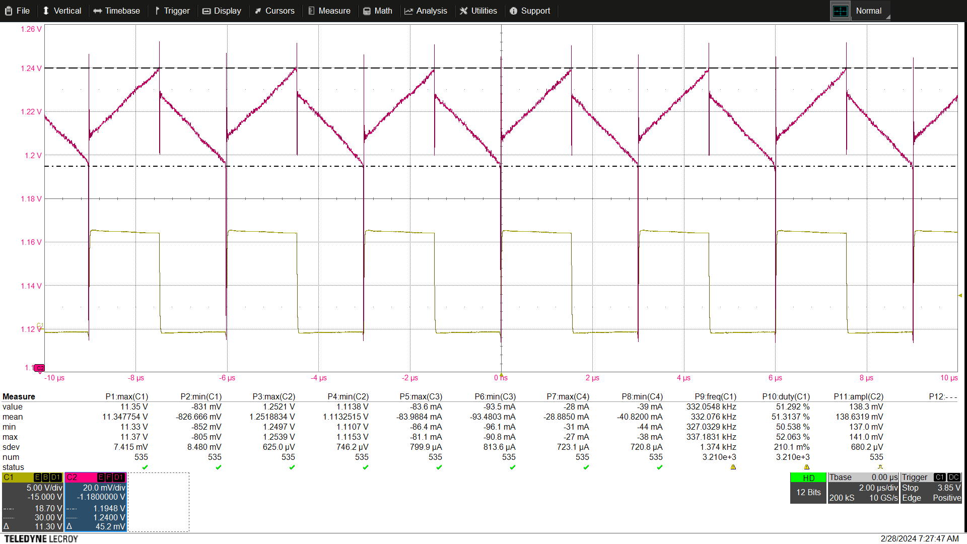
I started designing with WeBench a buck converter using the LM5164QDDARQ1. I changed some values to reducde the part diversity in my overall deisgn (See WebenchDesign and Implemented design). With RRON being 47kOhm 1% 100ppm I would expect a switching frequency of Vout*2500/RRON = 5*2500/47 = 263.3kHz ... 268.64kHz if I take into consideration the 1% tolerance of the resistor. However, I measured frequencies between 288kHz and 337kHz depending on the line and load conditions. I have attached all measurements (CH1: TP315, CH2: TP320). Does someone have an idea why there is such a discrepance between the designed frequency and the measured one ?

 WBDesign_LM5164QDDARQ1_high_efficiency.pdf

  • Hi Antoine,

    There are two possibilities I can think of:

    1) If you operate in lighter-load conditions, the converter is operating in DCM, so it can be load dependent. 

    2) It could be due to the injected ripple. Can you check the type 3 equations to make sure the values all fit the restrictions and then check again?

    Thanks,

    Richard

  • HI Richard,

    Thanks for your reply.

    1) If it operated in DCM, the switching node voltage (CH1) would not look like this, but it would have some ringing when the current reaches zero since the IC feature a diode emulation. So I assume it is always operating in CCM. My calculations also result in CCM operation for all operating conditions.

    2) All values of the ripple injection network fit the restrictions. Moreover the measurements (CH2) confirm a good ripple injection network design.

    Regards,

    Antoine

  • Hi Antoine,

    Sorry, I didn't take a good look at your waveforms you attached, and yes you're right- the part is always operate in CCM. 

    From discussing with the team, it looks like you see about a +/-20% deviation (more or less) which can happen with the on-time and off-time generators, since it is likely that there is an internal capacitor that will also have some range of tolerances. If that is a large concern, it may be better to pick a peak current mode device with a tighter frequency range.

    Thanks,

    Richard

  • Hi Richard,

    Ok ! Can I just add 20% tolerance on the value 2500 from the datasheet (equation 13) to calculate my expected frequency range ?

    I find it quite strange because the frequency is not just out of tolerance but it is spreading depending on operating points.

    Thanks,

    Antoine

  • Hi Antoine,

    Yes, that should work. 

    Thanks,

    Richard