


In my current application a three phase 2 level inverter is used to control a PMSM.
I'm using UCC21530-Q1 to drive SIC mosfet. Swtiching frequency is 20 kHz and switching speed in the range of 50 ns.
min and max duty cycle is 4 / 96 %
We use boostrap capacitor (1uF) to supply high side mosfet with a 10 ohm resistor + 1200V diode
We also use negative Bias with Single Power Supply and Zener Diode in Gate Drive Path as shown in figure 9.4 in component datasheet
The misunderstood we are facing:
In a first test, PWM was set at 50 % (minus DT), fixed value. DC bus voltage was 60V.
As you can see, the voltage at boostrap capacitor is quite stable with high frequency “oscillation”. Everything works as expected. After 15s we shut down the gate driver enabling to see how many time is needed to deplete boostrap capacitor.
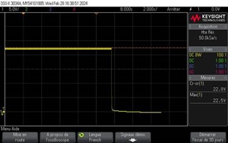
Measure of boostrap capacitor voltage
In a second test, we applied same condition, except one thing. Someone was turning back and forth PMSM rotorshaft by hand. Again duty cycle was fixed at 50%
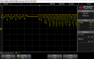
Measure of boostrap capacitor voltage
I’m wondering the different value i'm seeing. In the first 1.5s the ramp up and ramp down are very slow. Then bettween 1.6 to 2.3s voltage stay constant but below the nominal value. Finally from 2.5 to 5s, ramp up / ramp down are faster and the lowest value is near 0V. Do you have any idea explaining this behavior ?

