This thread has been locked.

If you have a related question, please click the "Ask a related question" button in the top right corner. The newly created question will be automatically linked to this question.

BQ51003: Waveform at FOD and ILIM pins

Part Number: BQ51003

Dear TI support team,

I am working on a design including the BQ51003 as a wireless receiver. For some reason the charging is interrupted occasionally, so I am currently trying to identify the root-cause for it.

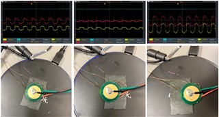
When investigating the on-board signals that potentially could trigger a shutdown of the output voltage, I observed that the voltages at the FOD and ILIM pins seem to be highly affected by shielding different areas of my PCB. To do so, I have added an additional ferrite sheet between the receiver coil and the PCB and moved the PCB slowly in different directions. The receiver coil was always centred underneath the ferrite sheet during that test.

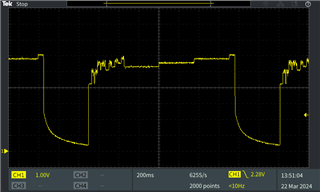
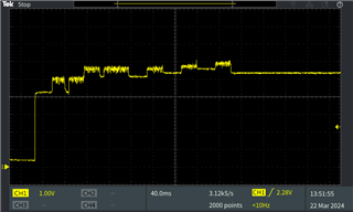
What I see is that the AC component of the signals changes significantly and also that the likelihood of the power transfer to be interrupted changes. The yellow waveform at CH1 represents the signal at the FOD pin and the red waveform at CH2 represents the signal at the ILIM pin. Unfortunately, I could not find the waveforms for these two pins in the datasheet to compare them to my measurement results, so I would kindly ask for your support to evaluate them. Is there even an AC component to be expected for these two signals or does it result from the magnetic field coupling into the signals? Also, what are the precise thresholds for these two pins to trigger the shutdown of the output voltage?

I observed that the solution to the right leads to the best test results in terms of continuous charging. Is that to be expected for the corresponding waveforms?

Please let me know if any additional information is required by you to support in this regards.

Thank you and I am looking forward to your reply!

Best regards,

Leonhard 

  • I would like to correct the labelling of the waveforms:

    • CH1 (yellow): FOD at pin
    • CH2 (blue): RECT at pin
    • CH3 (red): ILIM at pin
  • For some reason the charging is interrupted occasionally, so I am currently trying to identify the root-cause for it.

    My first suspect will be a communications issue. The TX need to get a good packet from the RX every 1.5 sec or it will stop power transfer and restart.

    When power transfer stops does it restart and how quickly?

    Can you send a schematic and info on your coil for review?

  • Hi Bill,
    thanks for your response!

    Sometimes the power transfer restarts after a few seconds (between 2 and maybe 10 seconds) and sometimes it does not restart at all. So far I could not observe any consistent pattern here, but it seems like this behaviour also varies dependent on the shielded area of the PCB.
    Do you have any recommendation on how I can evaluate the packets received by the transmitter to check for it? 

    Please find below the schematic including the part number of the coil:

  • Hi Leonhard

    Can you take a scope capture of RECT pin when unit drops out, Looking for the Ping from transmitter, how quickly it tries to re-start.  The ping may have problems and power transfer may be delayed.  But if we see a ping it is indicating not a fault condition.

  • Hi Bill,

    please apologize my delay in response.

    Once the power transfer is disturbed, it appears that the BQ51003 tries to continuously re-establish the power transfer after 400ms as it can be seen in the screenshot of the RECT pin below.

  • Hi Leonhard

    Thanks for the scope capture.  This points to a possible communications issue and not fault condition.

    The comm caps are 22nF with a Cs capacitor of 68nf -- try a comm cap in the 10nF to 15nF range.

  • Hi Bill,
    I have tried 12nF for the two COMM caps C1 and C6 but couldn't not observe any change in behaviour at the RECT pin.
    Additionally I have also tested 47nF which led to a stronger (larger amplitude) communication signal, but the charging is still interrupted after a few seconds.
    Then I have once more added a large ferrite sheet between the receiver coil and the PCB which fully eliminated the the dropouts at the RECT pin.
    Any idea what else I could look into? Doesn't it seem more like a fault condition appearing since the shielding has such a large impact on the performance?

  • Then I have once more added a large ferrite sheet between the receiver coil and the PCB which fully eliminated the the dropouts at the RECT pin.

    This would prevent the AC field from TX entering PCB and heating them and act as FOD fault.  But for a fault should not restart. 

    Also will change the RX coil tuning by changing L value.

    Another test would be to separate the coil and PCB / Unit and only place coil on TX, in AC field.  The coil can be extended using wire 3 to 6 inches.

  • Another test would be to separate the coil and PCB / Unit and only place coil on TX, in AC field.  The coil can be extended using wire 3 to 6 inches.

    Placing the PCB outside the vicinity of the RX coil also leads to positive results in terms of avoiding the dropouts.

    To me it seems very much like some kind of fault is triggering the IC to shutdown. That's also why I originally requested some explanation of the waveforms at the FOD and ILIM pin to understand if they look as intended.
    Is it somehow possible to artificially disable these two pins by pulling them to specific voltage levels? The idea behind is to confirm or exclude them as root-cause for the shutdowns.

  • Is there even an AC component to be expected for these two signals or does it result from the magnetic field coupling into the signals? Also, what are the precise thresholds for these two pins to trigger the shutdown of the output voltage?

    The ILIM and FOD pins should be DC signal.

    ILIM is a sample of output current at a ratio of 1 to 262.  The voltage developed on R-ILIM and R-FOD will be used for current limit when it reaches 1.2V.

    The voltage developed on R-FOD is used to generate the Received Power Packet sent to TX every 1.5 sec.  This tells the TX how much power the RX has received for Foreign Object Detection.

    ILIM will not be a problem until the voltage reaches 1.2V.

    FOD will depend on the TX to make a decision if power loss is too high.