Other Parts Discussed in Thread: DRV8245-Q1, DRV8873,
Hello Team,
We want to design an H Bridge circuit to drive a DC Motor.
The motor is a 12V DC motor with a maximum current of 2A.
The inrush can be up to 10A but for only few micro seconds.
My confusion is with the back emf of the DC Motor.
Can you please clarify the following doubts I am having.
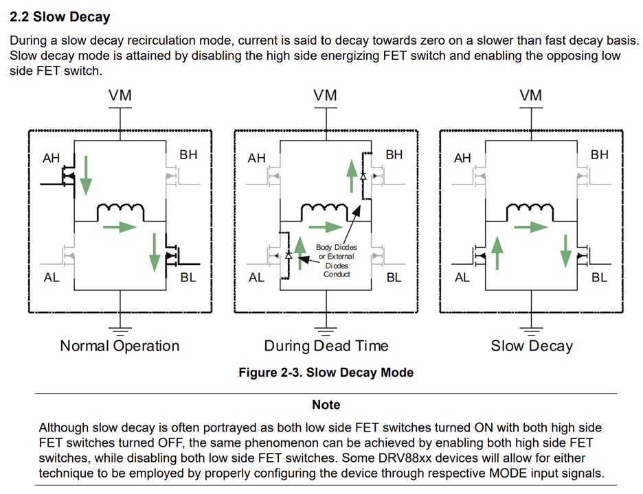
1). Is this the discharge path of the back emf.
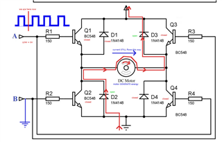
That is from the motor to the high side FET and back to the motor through the power supply and the low side FET at the opposite side?.
2). Can I use a bidirectional TVS diode with a breakdown voltage greater than 15V across the Motor leads to clamp the reverse voltage due to back emf?.
3). What will happen/ or how will the motor discharge if the power supply is removed abruptly?.
4). If the power is valid throughout the operation, the MOSFETs Q2 and Q3 will act as the discharge path for the motor and we don't need any control over then since they are just diodes.
If such a simple approach is available, then why should we go with some complex decay modes mentioned in the application note?.
5). The device we are planning is a test system. One of the test will be this motor driving.
So we are planning to place the DC motor in a separate PCB (like a test jig PCB) to which our PCB under test (having H Bridge) will be connected via relays. This will greatly reduce the wiring time for testing.
When the power to the test jig PCB is disturbed, the relay will disconnect while in the middle of the motor operation. So there is no place to discharge the back emf.
Can I use a bidirectional TVS diode with a breakdown voltage greater than 15V across the Motor leads to clamp the reverse voltage due to back emf in this scenario?.
I have observed some scenarios in our dotted PCB like the MOSEFTs in the H Bridge got damaged when the power to the relay is disconnected and reestablished again. What could be the reason for this?
6). What will happen to a motor if a safe discharge path is not given?
Looking for your reply