This thread has been locked.

If you have a related question, please click the "Ask a related question" button in the top right corner. The newly created question will be automatically linked to this question.

LM25184: LM25184 inrush current

Part Number: LM25184

Hi Team,

My customer Moxa using LM25184 for PLC isolation power, however they got high inrush current with power recycling test (5s).

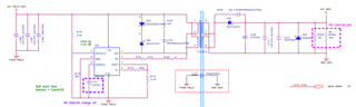
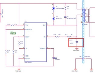
below is customer schematic 

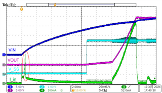
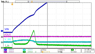
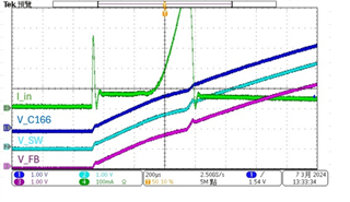
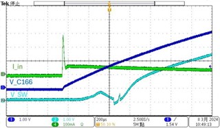
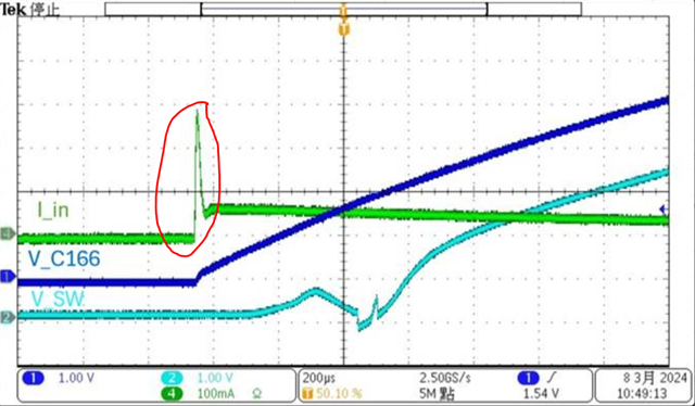
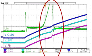
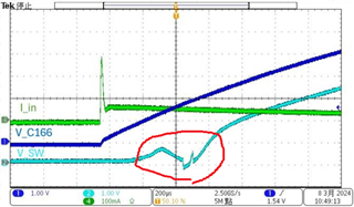
the inrush current waveform measurement, 

Customer would like to know how to prevent the inrush current? any suggestion to resolve this issue?

Thanks & Regards

Eddie Chou

  • Hi Eddie,

    Thank you for posting.  It seems the external 1uF capacitor held voltage during power recycling and hence prevent soft-start in the new power up.  Do you really need 1uF there? Can you simply use the internal 6ms by deleting the 1uF external soft start capacitor, and see if it meets your performance requirement?

    Thanks,

    Youhao

  • Hi Youhao, 

    The waveform customer shown Vcc is from 0V so customer think ss should not the issue. 

    Customer also did some experiment with transformer removed ( T4、D36、C170 remove from circuit)

    and got SW toggle waveform below,  and they concern the MOSFET turn on in this period which may cause inrush current. 

    Can you help explain what might this toggle during power up?

    Additional question from customer, they meet EMI issue and add 1nF on SW pin to reduce the EMI but efficiency become worse. 

    Do we have any suggest or application note for EMI improvement? Thanks. 

    Thanks & Regards

    Eddie 

  • Hi Eddi,

    Since the EN is controlled by input voltage via a resistor divider, yes the IC can turn on when EN exceeds the turn-on threshold.  Because you have large capacitor at SS pin, it may not get fully discharged during power recycling, then you can lose soft-start. Please also monitor SS voltage.  A quick test by removing the 1uF at the SS pin to see if it is related.

    To resolve EMI problem, you should not place a capacitor across SW and GND for it dumps power into the IC MOSFET.  Please delete the capacitor there.   Let us know at which frequency range they failed EMI, then we can try to suggest an effective mitigation.

    Thanks,

    Youhao

  • Hi Youhao, 

    We suggest customer remove 1uF at the SS pin, but still find the inrush current during power up. do you have other suggestion?

    Thanks & Regards

    Eddie 

  • Hi Eddie,

    Hope I did not misunderstand the issue.  By inrush Do you mean the current pulse at the beginning?

    Thanks,

    Youhao

  • Hi Youhao,

    Sorry for confusing you, the inrush concerned by customer is the 2nd peak current, 

    Customer tried remove transformer and 2nd inrush current disappeared but they see SW voltage toggle to 0V at the same position.  

    Customer think this might cause the inrush. (internal MOSFET turn on)

    Thanks & Regards

    Eddie 

  • Hi Eddie,

    Thank you for the clarification.  Usually the internal SS (namely no external cap at SS) would take about 6ms if SS is successfully reset before the next turn-on in this repetitive power recycling test. With 1uF, the SS should take  200ms according to datasheet equation (12).  However 1st scope picture shows the inrush pulse in less than 1ms.  This is why I think the 1uF was not successfully reset and suggest to remove it.

    May I bother you to get one more scope picture showing the following 4 traces at the same time?

    1. Vin at IC VIN pin

    2. I_in

    3. SS voltage

    4. Vout

    Thanks,

    Youhao

  • Hi Youhao,

    Please refer to below waveform with 1. Vin 2. I_in 3. SS voltage 4. Vout.

    They power on /off cycle is 5s period. 

    Thanks & Regards

    Eddie

  • Hi Eddie,

    Thank you for the scope pictures.  May I guess those were taken without 1uF SS capacitor, right?  The ss voltage does not look correct in the first page, for being much faster than the internally fixed ~6ms, not to mention with either 0.22uF or 1uF showing in their two schematics above. 

    In the second picture, I do not understand why SS has the small bump at the beginning.  It is not the expected behavior of the IC.  Also, the inrush current in the second picture is just ~300mA, does the customer complain about such inrush?

    Would you help clarify these while I am digesting the info?

    Thanks,

    Youhao