This thread has been locked.

If you have a related question, please click the "Ask a related question" button in the top right corner. The newly created question will be automatically linked to this question.

UCC21750-Q1: Questions related to VCC supply current and AIN function

Part Number: UCC21750-Q1
Other Parts Discussed in Thread: UCC21750

Hi Expert, 

Two questions would like to check with you. 

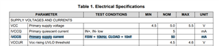
  1. May I know the maximum supply current for VCC pin that customer should consider? I can only find the VCC quiescent current (4mA max). But not sure the max supply current for VCC. 
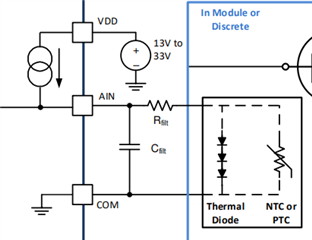
  2. For the AIN, customer would like to use this pin to sense external thermal resistor. I saw there have internal current source for AIN. Just would like to double check with you that customer do not need external power supply for thermal resistor sensing. 

Thanks!

Ethan Wen

  • Hi Ethan,

    1. VCC quiescent current is the supply current for the primary die (for INP =VCC) , there is a Temp Vs IVcc plot in page 12, at VCC=5V, the IVCC is around 4.5mA-  these are all for AIN=2V case. If the AIN =0V, then the APWM Duty cycle will be higher and will have higher current (don't have exact number) though. You can plan around 2mA higher (50% higher)

    2. Yes AIN pin can be used to sense external thermistor voltage and it supports current source and external current source is not needed.

  • Hi Sasikala, 

    Regarding to the VCC supply current, I saw some data in our EVM user guide as below. (https://www.ti.com/lit/ug/sluubx2b/sluubx2b.pdf)

    It says the supply current is 50mA when Fsw=10KHZ, CLOAD=10nF. It is higher than what you provide. It makes me confuse. 

    The background is that customer will have 12 pcs UCC21750 on board and we need the accurate number to confirm the VCC source capability. 

    So please help check the exact number. 

    Thanks!

    Ethan Wen

  • Hi Ethan,

    The VCC current doesn't increase wrt to switching frequency - the switching frequency vs IVCC is plotted in the datasheet and its flat irrespective of the switching frequency. Only the VDD current will increase with switching frequency. 

    I believe that the customer is interested to understand the Vcc bias current right -or VDD current?

    What is the expected typical AIN voltage in the system?

    Thanks

    Sasi

  • hi Sasi, 

    I don't quite understand the difference between VCC bias current and VCC current. 

    In short, customer is trying to design a 5V power supply for VCC pin. And they would like to know the max number of VCC current since they will have 12 pcs 21750 on board. And all the VCC come from one 5V power supply. 

    Regarding to the AIN voltage, I think this is not related to the VCC current, correct? From below diagram, AIN current source comes from VDD. Customer would like to connect a NTC on AIN pin. 

    Thanks!

    Ethan Wen

  • Hi Ethan,

    If its VCC current (for pin 15), then IVCC / VCC bias current can be planned based on the datasheet plot below, as you see that IVCC changes based on Temp, VCC voltage level, not the frequency. You can consider max current of it with some additional buffer.

    Though AIN is supplied from Vdd,  APWM (reflecting AIN voltage) is on the primary side. So when the APWM Duty cycle is higher (when AIN < 2V) , then Vcc needs additional current to support it. Hope it helps.

    Thanks

    Sasi