Other Parts Discussed in Thread: UCC2894
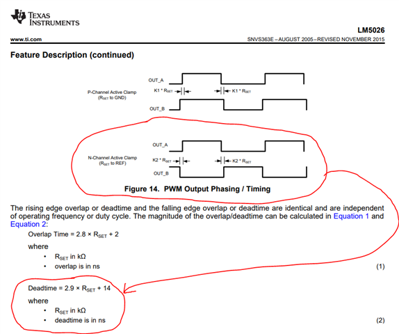
LM5026: the datasheet indicates 2 reset possibilities: P-MOSFET & N-MOSFET.
Plenty of examples for the P-MOSFET and it works.
Not a single example for connecting the N-MOSFET and any attempt to use one (in the spirit of the chip) has blown the LM5026.
I was hoping to speak to a Ti application Engineer to know what was intended, but no... just a forum, after 4 days of fight with a registration (error 403!).
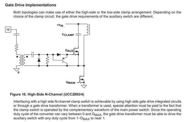
How do one connects a N-MOSFET for resetting the core of the forward converter?