


I've been in these forums recently to stabilize a LM25148 converter. The problem was identified as noise and fixed by slightly slowing down the high side gate drive signal. The Converter works fine at its designed output voltage and across its output current range.
I'm now trying to implement a second feedback loop to introduce constant current regulation. The schematic below reflects the current status of my protoype:
While troubleshooting I came across the app note snvaa85 which implements this control in the exact same way. The app note does note explain the conditions for stability on this secondary loop, simply saying
"The values of capacitors C2 and C3 in the differential amplifier circuit are related to the CC circuit loop. Since both the CC and CV circuits are added to the FB pin, to stabilize the loop, it is necessary to slow down the CC loop as much as possible. We recommend that the values of C2 and C3 be between 1 nF and 10 nF."
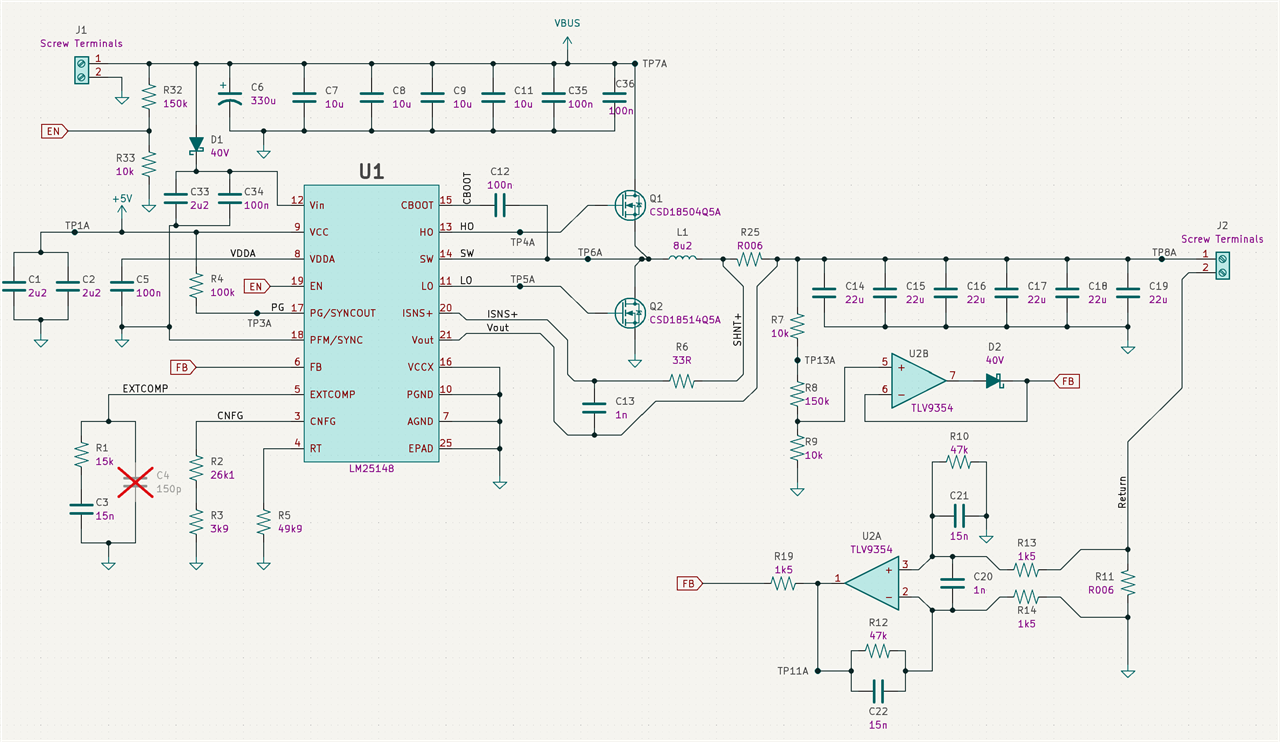
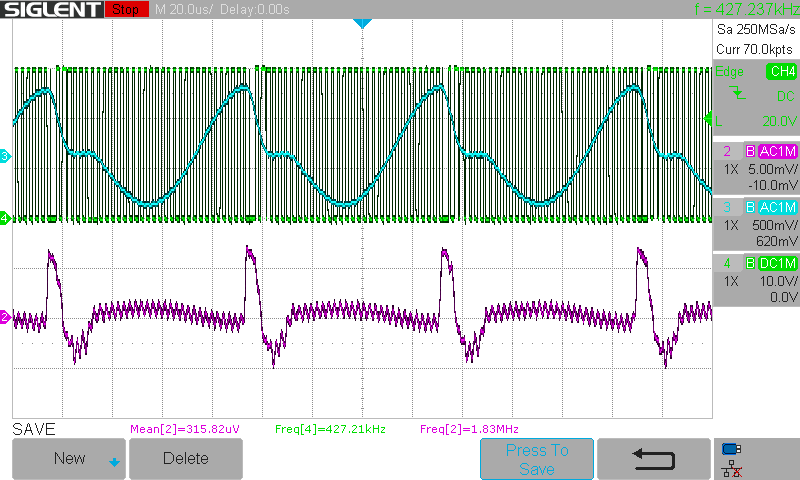
Along these lines I tried many values of C21 and C22. the following scope shots all show the constant current mode when the load voltage is just below the converter design voltage (200mV drop). Green is the SW node, pink is the amplified current measurement (AC coupled) at TP11A, and blue is the output voltage (also AC coupled). Note the scale is not always the same.
With 1n:
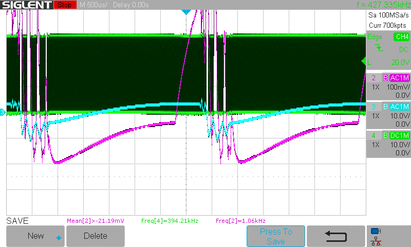
With 47n:
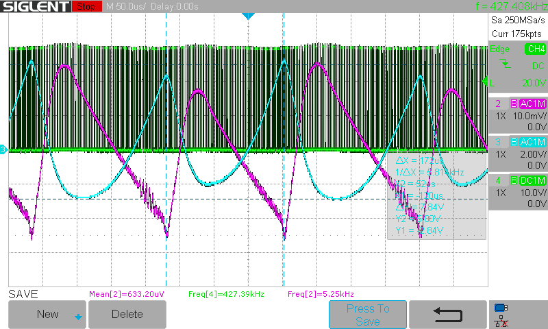
With 100n:
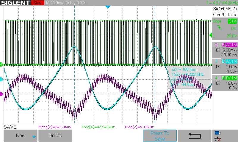
With 200n:
As shown, performance seems more stable with a "slower" amplifier, but never reaches a good steady state and always oscillates more than an order of magnitude below switching frequency.
That app note obviously simplifies the design, but where should I go from here? Other resources also seem to gloss over the interactions of two feedback loops but it seems like the fundamental topology of my circuit makes sense. Additional resources or strategy suggestions would be appreciated.
My current thoughts are to either adjust the compensation network for this feedback method as well, or change my feedback amp topology. Maybe some sort of integrator?
I feel like I'm missing a basic principle of multiple feedback loops, pointing me in the right direction might be enough for now. Thanks as always

