This thread has been locked.
If you have a related question, please click the "Ask a related question" button in the top right corner. The newly created question will be automatically linked to this question.
Dear TI team,
I have some issues with a circuit that was assigned to me: the circuit was previously designed with a tps55289 by mistake, as the application wasn't intended to be controlled by I2C. We replaced it with a tps552892-Q1.
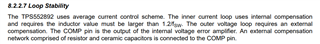
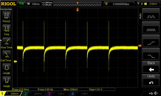
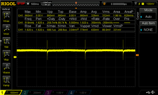
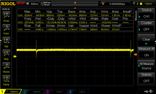
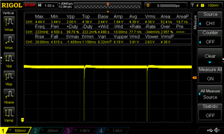
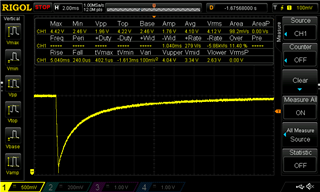
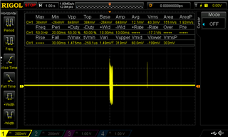
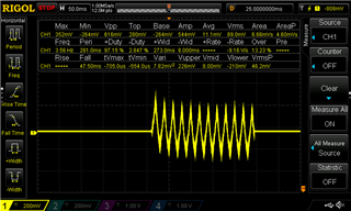
For the circuit attached, Vin is from 11 to 17 V, the desired Vout is 12 V and the Iout max is 6 A. After placing all the components on the PCB I have an strange behaviour, and it makes me doubt about the soldering: when I turn on the circuit and set a Vin from 11 to 17 V, the open-circuit output has a Vout of 4.3 V, and the power supply states an input of 0 A. The temperature of the IC is stable around 25ºC. After that, if I disconnect the supply and connect it again, the Vout is around 1 V, the I around 0.150 A and the temperature can go up to 60ºC in minutes. After 5/6 minutes, the output gows back to 4.3 V.
L1 is IHLP3232DZER3R3M01.
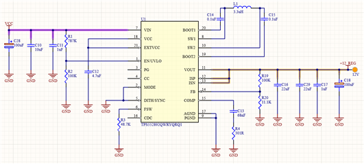
Can you help me checking that eveything is ok within the schematic?
I can't find why I have a 4 V ouput instead of the 12 V. Apparently, there are no shorts between the pins and on the EN/UVLO pin I have more than 1.2 V.
What kind of behaviour should I expect if the IC is not well soldered?
Thanks for your help,
Juanjo.
Hi Juanjo.
Thank you for reaching out. May I know what is the application here?
Please check C12 voltage to see if it is 5.2V VCC voltage. Can you provide SW1, SW2, IL, Vout waveforms?
Can you provide part number or datasheet of C16, C18 and C29? I can see some design problems and I will five you some feedback later.
Regards,
Mulin
Hi Juanjo,
Below is my feedback:
1.Use 4.7uH inductor with Isat>8A.
2.Add 2.2nF+2.2ohm RC snubber in SW1 and SW2.
3.Add a 0402 0.1uF ceramic capacitor in Vout pin and put it as close as to the device.
4.Recommend to connect mode to VCC to choose PWM mode in auto application.
5.Recommend to add a 10nF capacitor in dithering pin in auto application for better EMI.
6.Recommend to change R2 to 150k for some margin in case the VCC is unstable.
4.The compensation parameters is unsuitable. Try C13=10nF and R4=5k first to see if it is stable.
Please also answer my question above.
Regards,
Mulin
Hi Mulin!
First of all, thanks for your replies and here are my answers:
1. In this application we will have a rectified Vcc (the signal will pass trough a coil, full-bridge rectifier + big capacitor filter) and then +12_REG will suplly to a different board and an ESP.
2. C12 has 5.3 V.
3. Waveforms (all were measured with a Vcc of 16 V):
SW1:
SW2:
Vout:
IL**:
* I don't have any current probes around so I used a 0.169 ohm shunt resistor method for this purpose.
4. The part numbers you asked:
- C16 & 29: KYOCERA AVX 12063D226MAT2A
- C18: Wurth Elektronik 865080653016
Regards,
Juanjo.
PS: I will wait for you to check the waveforms to implement your recommendations.
Hi Juanjo,
The chip is not working normally now. I think we need to rule out the root cause one by one.
1. Change R2 to 200k. Check Vin, EN, SW1, Vout waveform and put them in one screenshot. It hard to tell the chip working condition with separate waveforms. This action is to check whether input voltage is pulled down when the chip start to work and the EN voltage drops below threshold, causing the periodic voltage drop.
2.Change C13=10nF and R4=5k . From the inductor current, the loop is not stable. Let's check the inductor current waveform in this compensation parameter to see if the loop can be stable. Put inductor current, SW1, SW2 Vout waveforms in one screenshoot.
3.Please double check whether the chip, inductor and other component are well populated. Check if there is any short condition.
I will wait for your feedback. Thank you.
Regards,
Mulin
Hi Mulin!
Thanks for your answer, I am working on the things you asked, and I have one quick question: do you need me to check the waveforms with the new components (step 1 with R2 200K and step 2 with C13 10nF / R4 5K) with the previous configuration or with the one you already told me? I mean, with the 3.3 uH inductor or with 4.7 uH + RC snubber + 0402 capacitor. If you don't mind, this will take a couple of days as I will need to order new components (don't have any 2.2 ohm resistors).
Regards,
Juanjo.
Hi Juanjo,
You can primarily check step 1 with only R2 changed and see if it will be better. About step two, you can wait for the components(4.7 uH + RC snubber + 0402 capacitor).
Please feel free to let me know the result any time. Finding out the root cause may take some time and I am glad to help.
Regards.
Mulin
Hi again Mulin!
Sorry for the delay, but finally I managed to come back to this issue.
So I checked again looking for shorts and cheked if every component was well populated before proceeding with step 2. As I had doubts regarding the tps itself, I decided to change it with a new one (you know how electronics work, you always buy one extra component just in case) and it started working, with a Vout between 12.1 and 12.14 V!
Before closing this ticket, I would like to ask you if I should implent the first recommendations you told me 14 days ago (RC snubber, 4.7 uH, etc.) or should I leave it as it is now? (I mean, with the 3.6 uH coil, and the R2 changed of step 1).
Thanks for all your help,
Juanjo.
Hi again Juan,
Happy to hear your feedback. I strongly recommend that you follow my above advice to modify the schematic. 4.7uH is required for internal stability.
Feel free to contact us if you have any other problem.
Regards,
Mulin