This thread has been locked.

If you have a related question, please click the "Ask a related question" button in the top right corner. The newly created question will be automatically linked to this question.

LM3481: Feedback method for Flyback converter to act as an isolated voltage buffer with variable input voltage

Part Number: LM3481
Other Parts Discussed in Thread: TL431,

Traditionally flyback converters are designed to obtain fixed output voltages at variable input voltage ranges with galvanic isolation and literature is available widely for such designs.

There, the Error amplifier is placed at the output with a voltage reference (ex. TL431).

I would like to know the feasibility for designing a flyback converter whose output follows the Variable input voltage (Vout = Vin). examples: Vin range= 5V to 12V,  when Vin = 5V Vout =5V, Vin = 9V Vout =9V and Vin = 12V Vout =12V etc.

I feel like placing an error amplifier on the primary-side theoretically. But I guess that there may be standard design solution or probably not feasible in practice. 

How to realize a such a design ?

  • Hello Nishshanka,

    Thanks for reaching out to us via e2e.

    This is an interesting concept. Basically an "isolated wire".
    So, if I get it right, you need to have full isolation.

    Which load current are you looking for?

    All our controllers are basically designed to stabilize an output voltage.
    There are newer devices with a Track Pin where you can feed an input voltage into that pin to define the output voltage.
    But these parts do not support a flyback topology.

    If you disconnect the voltage feedback loop from the output voltage and control it by the input voltage instead,
    you will lose the regulation of the output voltage in case of a changing load.

    If the load is constant, this might still work.

    For a changing load, you must mix the voltage feedback from the output with the information about the input voltage.

    For non-isolated topologies, where the output voltage is connected to a resistor divider and the divided down voltage is fed into a feedback pin,
    we do support the concept of mixing that feedback voltage with another current (e.g. to allow for selectable targeted output voltages).

    In case of an isolated flyback the feedback divider cannot work, as it would break the isolation.
    The problem is that the error amplifier (e.g. TL431) has to sit on the secondary side.
    So you would need some additional isolated amplifier / trans-impedance element to bring the information of the input voltage to the secondary side (as a current that you can mix into the feedback path).

    I do not know of any document which would describe such an overall concept.
    But the Power Stage Designer tool can help to create the current mixing stage.

    Best regards
    Harry

  • Hi Harry,

    Thank you for your detailed prompt response.

    The term "isolated wire" is a perfect name :-)

    Yes. I need full isolation and output current is 2A-Maximum (Load is variable).

    I have to make output voltage variable to avoid drawing over current from the primary side (in a typical fixed voltage output converter when the load is unaware about the source rating) because input voltage source can have different power ratings (like USB ports).

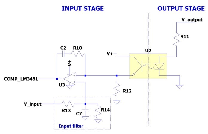
    I came up with a concept diagram as attached. Will such a design be stable practically?

    Thank you,
    Best regards,
    Nishshanka~

  • Hello Nishshanka,

    As a basic concept your circuitry would do what it should do.
    But the problem is that the COMP pin has an internal current source.
    Therefore, you must not use that external amplifier in a way that it will drive against the COMP pin.

    You would need to come up with some kind of resistive load or resistive divider which is connected to that pin.
    The maximum allowed external voltage "feed" is a 4.7k pull-up resistor from VCC to the COMP pin, which is needed to supply enough current for the opto-coupler (see LM3481-FlybackEVM).

    As you are mixing the output- and input-feedback, you may try feeding that signal into the Feedback pin (I think it needs to be inverted in that case).

    The big challenge will be finding the right distribution of the influence between the two feedback signals (Vin and Vout).

    Also, when using the feedback pin, you will need to do some step response tests to find a good compensation network which will be stable in all cases.
    We cannot really help you with a calculation method.

    Best regards
    Harry