


Other Parts Discussed in Thread: CSD18540Q5B, BQ76942, MSPM0L1306
Hi team,
I want to understand better the power losses and efficiency in our circuit. Regarding to this I have the following charger circuit:
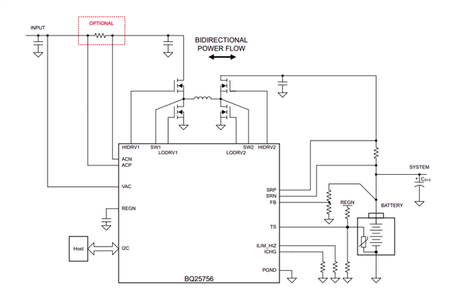
- With 5mOhm for RAC_SNS and VAC_SNS.
- L=15uHy with DCR=33mOhm
- CSD18540Q5B for the full bridge
- A TPS25750D as previous stage
- A BQ76942 as following stage (BMS+BatteryPack)
- MSPM0L1306 as main MCU controller
Doing a charge process, with 2A (40V) as ILoad we have 4.77A and 20V as profile. The chip datasheet express at that profile near to 96% of efficiency. With this loss we estimate 3.93W (including mosfets, inductor, ESR from capacitors, chip, and resistors), but we have 10W of difference between theory and implementation.
How should I proceed? Taking (4.77A*20V)*(chip efficiency) as input power and then substract the components loss? Because I cannot understand to what refers the efficiency from the datasheet.
What does it refers? For example, if I have ideal components with no losses: If I give to this chip 100W I will obtain 96W at the output port. Where does this power difference has explanation? Or the efficiency in the chip takes in account the different components power losses?
If you want I can give the python script with all these calculous.
Best regards
Nicolas
