This thread has been locked.

If you have a related question, please click the "Ask a related question" button in the top right corner. The newly created question will be automatically linked to this question.

TPS92638-Q1: TPS92638-Q1

Part Number: TPS92638-Q1

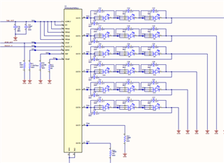
How can we connect unused IOUT pin, let's say if i only have 6 channel led, how should I end remaining two channels in LED Driver?

  • Hi Ruchi,

    PWM1 controls OUT1/2, PWM2 controls OUT3/4. PWM3 controls OUT5/6, PWM4 controls OUT7/8.

    For example, if OUT7/8 are designed as unused pins, please pull down the PWM4 to GND, and leave OUT7/8 floating.

    BR,

    Hailee.

  • Hello Hailee, Thank you for your answer.

    Wouldn't it cause open load detection if we keep it floating and also what if OUT7/8 is grounded via 100K resistor, is it a correct implementation.

    PS: I am using this LED Driver without MCU, please refer the images below, pin out7/8 is not used, meanwhile I grounded it via resistor. Let me know the correct implementation if I am doing something wrong in it.

    Also if we are using mcu for LED driver, and we want to control one output, how do we do it because 1pwm is controlling two outputs.

  • Hi Ruchi,

    As you can see, the device detects the open load fault or short-circuit fault when the channel is on, if you connect the PWM4 to GND, that means the OUT7/8 won't have this fault detection.

    But if you want to control one output, and the other one is unused. It is recommended to add a resistor between OUT pin and GND, just like the picture you showed.

    BR,

    Hailee.