BQ79600-Q1: BQ79600 SPI Communication

Part Number: BQ79600-Q1
Other Parts Discussed in Thread: LAUNCHXL2-TMS57012, BQ79616EVM-021, BQ79600EVM, HALCOGEN, USB2ANY

Hello,

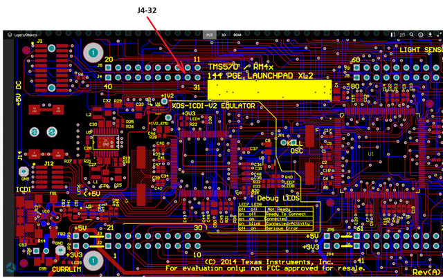
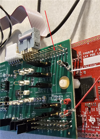
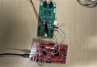
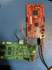
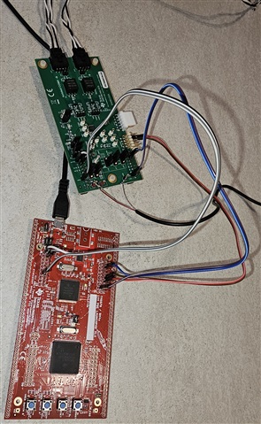
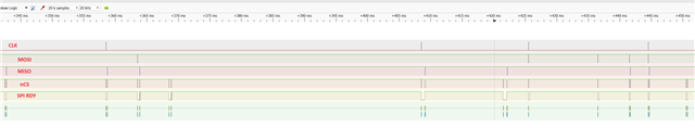
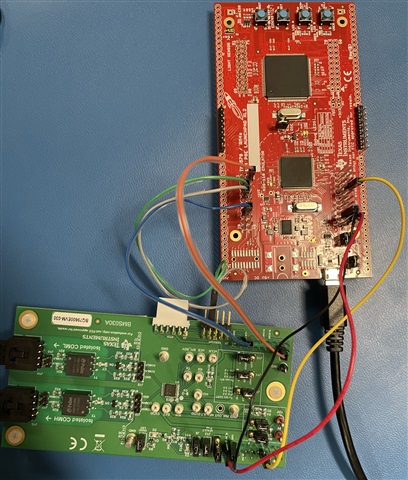
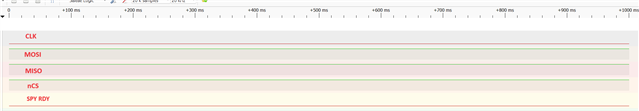
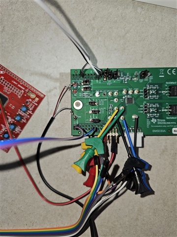
I use a TI example project for spi communication between TMS570 and BQ79600.

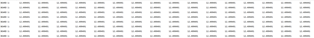
And trying to read out the voltage values.

But the values whitch I get back are much to high and same fo every channel.

Could you please take a look into the project and help to solve the problem.

Thank you in advance

Harry

BMS_SPI.zip

  • Harry,

    Ensure that you have connected the SPI_RDY pin on the BQ79600 connected to J4-32 (GIO PORTA[1]) on the TMS570. Your code has the behavior you describe when this connection is missing but works fine when it is in place.

    Regards,

    Ben

  • Hello Ben,

    is there a description of that some where in the manuells. Is there ajumper or sumthing simillar?
    Sorry!

    Thank you

    Harry

  • Harry,

    The SPI_RDY pin is detailed in section 7.3.2.1.2.2 of the BQ79600 datasheet. It looks like you got the SPI drivers from the 718 sample code and I do not know if there are more details to be found about the pin there. You can find it throughout the code, however, such as here:

    Regards,

    Ben

  • Hello Ben,

    This loop is in the SpiReadReg(....) function to. And I use the SpiReadReg to read the values.

    So if gioPORTA[1] would be allways equal to 0 the function would end up in a endless loop and I wouldn't be able to see the wrong values?

    Maybe I have explained my set up wrong?

    I use LAUNCHXL2-TMS57012,  BQ79600EVM and BQ79616EVM-021. All devices are connected according TI explanation.

    Thank you

    Harry

  • Harry,

    The SPI_RDY pin is an output from the BQ79600 is equal to one when it is ready to deliver data. Writes and pings do not require the SPI_RDY pin and so you were able to wake the device and turn off the communication timeout without issue. However, during a read the BQ79600 will drive the SPI_RDY pin to be low while the stack is processing the request, and only once the BQ79600 drives the SPI_RDY pin high is it ready to transmit.

    If the GIO PORTA[1] is not connected it is set to always be high and the code assumed the BQ79600 was ready to transmit when it wasn't. The MCU sent the clock signals that would have indicated to the BQ79600 to send its data, but it wasn't ready to send the data and sent all ones instead. The code you had did not check for CRC errors and just assumed the data was valid and displayed the maximum possible voltage (~12 V) for each cell on the console. 

    Regards,

    Ben

  • Ben,

    please take a look at the pictures.

       1. PCB Layout shows the position of  J4-32 (GIO PORTA[1]) on Launchpad

       2. Photo of connected devices. (SPI_RDY is connected with J4-32)

    It is just not posible to make wrong.

    Maybe a have to activate something on HALCogen?

    Best Regards

    Harry

  • Harry,

    To connect the boards in the way you have shown you need to move certain resistors on BQ79600. You need to move the resistor on R7 to R8 and the resistor on R9 to R10. I can see in the image you sent that you have not done this.

    You can connect the boards without changing these resistors by connecting the MOSI and MISO pins on the TMS570 to pins 7 and 8 of J4 (where the USB2ANY is plugged in) on the BQ79600. Otherwise the the pin connections are the same.

    Regards,

    Ben

  • Thank you Ben!

    A picture is worth a thousand words.

    Is there a description of this connection in TI manuals?

    Can you please send me your picture in a better resolution?

    Which interface (SPI or UART) is recommended by TI if MCU and the bridge are on the same PCB?

    Thank you in advance

    Harry

  • Harry,

    I do not know of an official description of this SPI setup, but it is the connection names are still the same. Here is another image (with the SPI_RDY pin correctly attached to GIO PORTA[1]). Hopefully it is in a better resolution.

    We do not have any such recommendations between UART or SPI. It is up to the customer to determine which is a better fit for their system.

    Regards,

    Ben

  • Hello Ben,

    I've connected the boards according to your photo. (Please see attached)

    The program sill delivers 12.499491 for each channel

    Sorry

    Harry

  • Harry,

    When you run the program do you see the green LED on the BQ79600 light up? This indicates that it has received a WAKE ping and has woken up. If this is not happening then either the device is not correctly receiving a WAKE ping or the device is no receiving the correct amount of power. 

    Either way, you should attach a logic analyzer to the RX, TX, SPI_CLK, nCS, and SPI_RDY test points on the BQ79600 to see what the device is receiving. If you could share those logs I might be able to glean more information.

    Regards,

    Ben

  • Ben,

    I see the green LED on BQ79600. It seems to be ok.

    With the logic analyser I will test in the next week

    Best Regards

    Harry

  • Hello Ben,

    Meanwhile, I have received the logic analyzer. 

    So I was able to record the communication between  BQAutoEval and BQ79600-Eval board.
     
    Then I have connected Launch-Pad and BQ79600.
    After switch on of the Launch-Pad, The BQ79600 light up. (LED D2=green and D3=red)
    But it seems like the SPI Ready signal is not there. (see picture bellow) 
    (I have connected the SPI_RDY Pin of the BQ79600 and Launch Pad  Pin32 (J4)).
    So the Launch-Pad and BQ79600 are not connunicate.
    After exactly 2 min.  the BQ79600 state changes to off (D2 and D3 are off).
    After that the Launch-Pad start to deliver wrong values.
    Best Regards
    Harry
  • Harry,

    You need to provide the appropriate voltage to either the 12V or 5V pins on the BQ79600 for it to work properly. Refer to the Quick Start Guide in the EVM User's Guide (link).

    Regards,

    Ben

  • Ben,

    I have provided 5V and 0.7A to BQ79600. 

    Best Regards

    Harry

  • Harry,

    What commands are you sending to the BQ79600? It does not look like anything is happening in the second logic analyzer picture you sent. Could you send the whole log? You can insert a file into these replies using the "Insert" button below the text box.

    Regards,

    Ben

  • Ben,

    please find attached the record file + project.

    Best Regards

    Harry

    Records.zipBQ79600_SPI_Sample_Code.zip

  • Harry,

    Thanks for providing those files. I can find no faults in the code. However, the logic analyzer file is unusable. The BQ796xx series of devices communicate to the MCU using a standard SPI protocol that has a clock with a frequency of 2 MHz. The file you shared appears to have a maximum precision of 20 kHz.

    If you are suppling 5 V to the BQ79600, double check that jumpers J1 and J3 are configured correctly. 

    Regards,

    Ben

  • Hallo Ben,

    please find attached a photo of jumpers (1, 3) and a new file with 2MHz.

    Are 0.7A OK or should I use more current?

    Best Regard

    Harry

     Records_2.zip

  • Harry,

    The logic analyzer log is still not at a sufficient resolution to be useful. The resolution should be much greater than 2 MHz, ideally around 20 Mhz. 

    The behavior with SPI_RDY dropping low indicates that you are sending a read command as the first command after the WAKE ping and the behavior with SPI_RDY staying low indicates you are overflowing the buffer. I cannot see anything immediately wrong with the code you sent me, we need the logic analyzer log.

    Regards,

    Ben

  • Harry,

    Additionally, ensure you are not forcing 0.7 A into the device. The device should be allowed to draw a normal amount of current (on the order of 10 mA, but definitely less than 100 mA). 

    Regards,

    Ben 

  • Ben,

    I use PulseView so I can only choose between 16MHz and 24MHz.
    So I have created 1 file with 16MHz resolution.
    Pulse view has a limitation with amount of samples you can record. (1T sample).
    With 24MHz, I'm not able to record the whole procedure between the start of the MCU and the start of delivering of wrong values.
    So I have made 2 files. Beginning of the cycle and end of the cycle.

    Best Regards

    Harry

    16MHz.zip24MHz.zip   

  • Ben,

    I'm using a normal power adaptor. 5V 0.7A.
    I think 0.7A will be max. current witch this adaptor is able to provide.

    Best Regards
    Harry