This thread has been locked.

If you have a related question, please click the "Ask a related question" button in the top right corner. The newly created question will be automatically linked to this question.

LM5169: Isolated power supplies

Part Number: LM5169

Hello,

I have designed two 24V isolated power supplies by using the LM5169 in Flybuck converter.

Could you please review the following schematic and give me your advice?

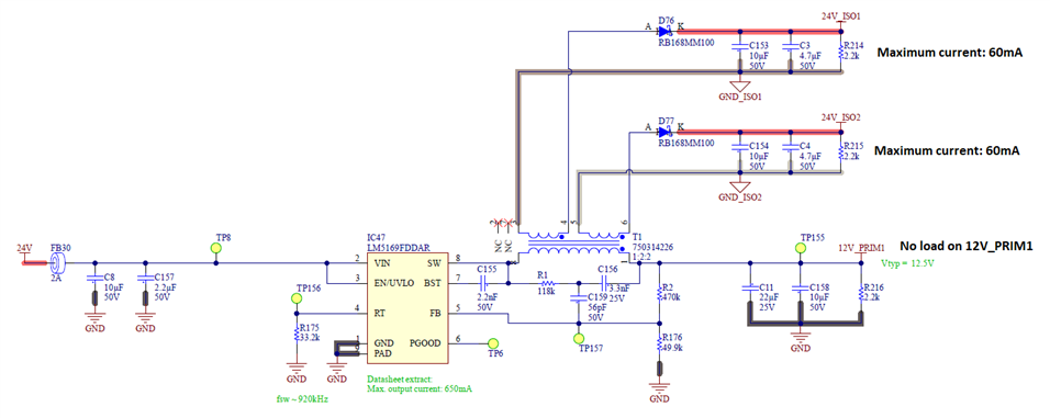
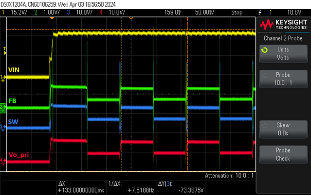
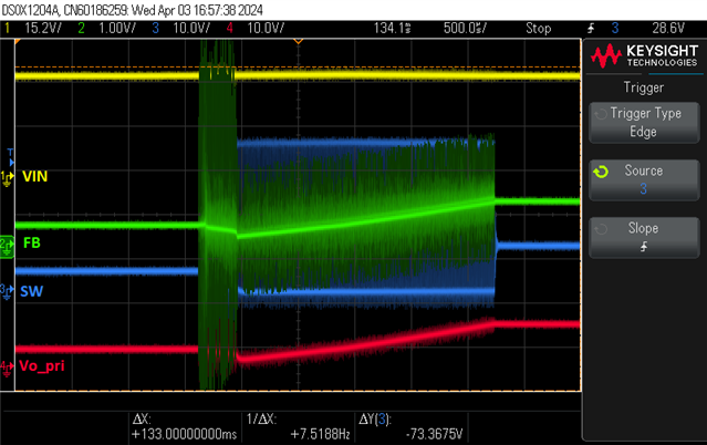
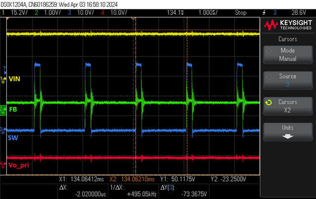
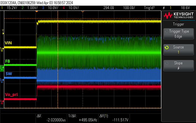
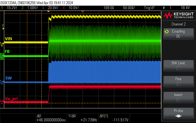
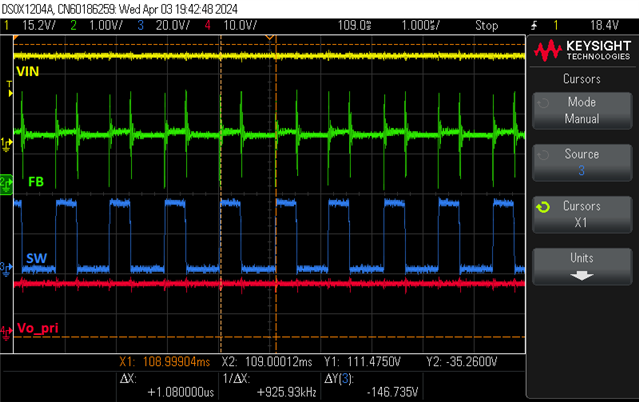
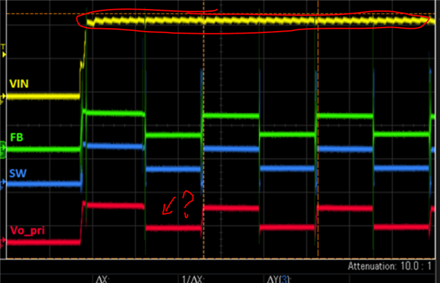
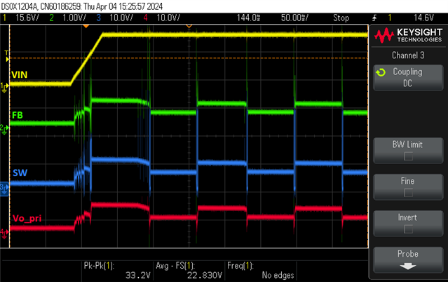
I have prototyped this schematic and I meet a problem at start-up.

To start correctly the 12V_PRIM1, I have to put a load on the primary side (100Ω for example).

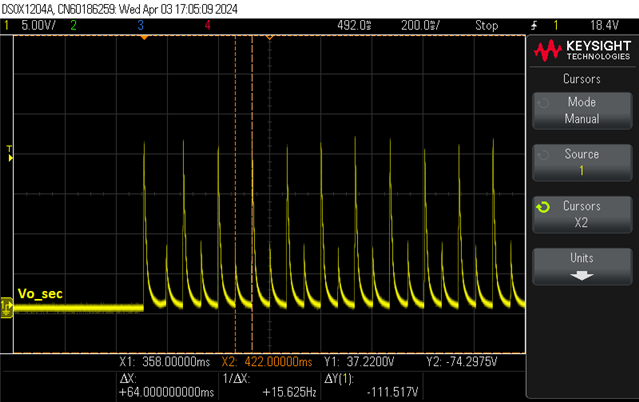
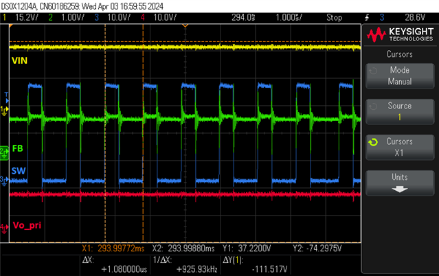
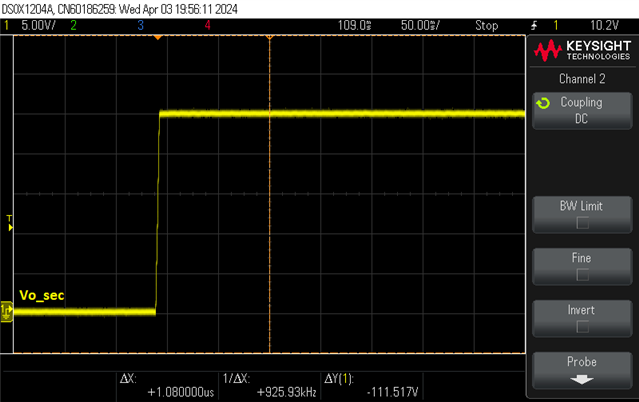
Then, when the DCDC is started, I can remove the load and the flybuck works correctly on the 12V_PRIM1, 24V_ISO1 and 24V_ISO2.

So I have a question, do we have to load the primary side if we only need both isolated power 24V_ISO1 and 24V_ISO2?

Thank you.

Best Regards

  • Hi Adrien,

    Thank you for designing with our products.  In my understanding the fly-buck design does not have to have a load on the primary side to start up. I also checked with another colleague who is very familiar with the device, and he confirmed my understanding, but he suggested to check to be sure that the customer uses "F" version of the IC.  

    I don't see any obvious problem in their schematic. To further investigate this, could you help get some key waveforms to show with and without primary load during startup?  Please show VIN, SW, Vo_pri and one of the 2nd Vout.  In another picture, show VIN, SW, Vo_pri and FB.

    Thanks,

    Youhao

  • Hi Youhao,

    First of all, thank you for the schematic review.

    For the device, I confirm that we use the F version (Reference: LM5169FDDAR).

    I take screenshots in several cases.

    - No load on Vo_pri, startup KO:

    During the transition phase, the SW pin starts to switch a moment then stops. However the switching frequency is not the one setted (please see following screenshots):

    Note that the FB signal seems to be noisy but it is caused by the ground return of the scope probe.

    - No load on Vo_pri, startup OK

    Sometimes the flybuck starts correctly.

    Switching frequency is the one setted by the dedicated resistor.

    - 100Ω load on Vo_pri, startup OK

    Thanks,

    Adrien

  • Hi Adrien,

    Thank you for the scope pictures. Please allow me some time to digest these. A quick question: do you have a long cable in the input line?  I see the input voltage fluctuate a lot which should be mostly flat during operation.  Beside, Vout has steps but you said it was OK for the first scope picture. Why do you think it is OK?  I just want not to misunderstand your comments of these scope pictures. 

    Thanks,

    Youhao

  • Hi Youhao,

    We have ripple on VIN because the input voltage comes from a 24V AC rectified to DC with a bridge rectifier.

    To dismiss a problem caused by the ripple on VIN, I also do the test with a 30V DC supply.

    Please see hereafter the screenshot, I have the same behaviour:

    For the first picture you mention, indeed the result is KO.

    Thank you.

    Adrien

  • Thank you Adrien.  I am studying this case and will update ASAP.

    Regards,

    Youhao

  • Hi Adrien,

    Sorry for the delay.  After studying this case, I am afraid the circuit hits the internal low side FET's negative current limit during startup.  It is because there is no load at the primary rail, then the reflected secondary current when the diodes are conducting make the primary current more negative which could trip the current limit.  If you have primary load, the load current itself would lift the inductor current when the secondary diodes conduct, and resulting in a less negative peak current which can prevent trip the limit.  

    Are you using an E-load CC mode for the secondary loads or resistor load?  If you are using CC mode, it may make start up more difficult. 

    Anyway, adding 100Ohm on the primary side is a not a small loss.  Could you a different approach to see if the startup issue can be resolved with much lower losses? I think it would work but please run a quick test to verify:  insert 5 Ohm resistor to each of the secondary diodes to limit the reflected negative current. Since your load is just 60mA, these two 5 Ohm resistor would cause a small fraction of the power than putting a 100 Ohm dummy load on the primary side.  

    Please let me know if you see any improvement.

    Best Regards,

    Youhao

  • Hi Youhao,

    Thank you for your great support.

    Indeed the problem was caused by the inrush current at start up.

    I have tested with inrush current limiters on each secondary voltages and the problem disappears.

    Thank you.

    Best Regards,

    Adrien