This thread has been locked.

If you have a related question, please click the "Ask a related question" button in the top right corner. The newly created question will be automatically linked to this question.

LM5013-Q1: Stability issues and bad performance at low temperature

Part Number: LM5013-Q1
Other Parts Discussed in Thread: LM5013

Hi,

I have designed a power board for my company using your LM5013-Q1. The board powers a rugged PC which we intend to sell as a premium product. I used your WEBENCH tool to help get a good design, or so I thought. Here´s the demands: Vin nom: +28V, max: +40V. Vout: +12.5V. Iout nom: 1A, max: 3.5A. Temp demands are -40°C to +65°C working environmental temp and -45°C to +80°C storage temp.

Our schematics for the circuit looks as follows:

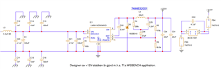
The ferrite beads and the extra capacitor at the output connector is for meeting EMC demands. When we tested the complete assembled unit all seemed fine. We performed a burn-in test with no problems.

But when we put the units in our climate chamber for a cold test in -40°C more than one third of all units refused to start! Only after some time in room temperature with power on they slowly were able to power the motherboard enough to start the PC. I quickly found out that the power board were unable to output a correct voltage in cold climate. But not in every unit, only some...

We sprayed cold spray to different areas on the power board to try to identify the problem to any particular component but Vout was only affected when we sprayed the LM5013 IC. Nothing happened when we tried to concentrate the cold to surrounding components, only when cooling the LM5013.

I started thinking if we might have damaged the boards somehow in our previous testing, but I had a panel with 7 new "untouched" boards directly from our supplier. We tested each board in the new panel by connecting them on the test bench to DC power in and to our PC for power out and then spraying them with cold spray. Turns out that of 7 board one was showing bad tendencies, one was more ore less useless while the rest was better. So the bad behaviour was there from the beginning.

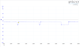
I scanned your web page for info on the LM5013 to see if there were something I might have missed or designed poorly. I found the " Stability Analysis and Design of COT Type-3 Ripple Circuit" which dealt with the stability of the circuit. I took the two bad boards and one OK board and hooked up my PicoScope to it. I used a resistive load of 8 ohm to load the output and started to test all about the boards.

I changed surrounding components testing different values but it wasn't until I changed the switching diode that things started to improve! The diode we had used was a VSSB310. It has an If (AV) of 3A and a Ifsm of 80A which I thought should be sufficient, but when I replaced it with a FSV12100V with If(AV) of 12A and Ifsm of 220A the board worked better. Now the board managed to keep the power up even at cold climate!
But why really? The LM5013 datasheet doesn't say that much about the switching diode and what parameters are the most important. What was it with our original diode that was insufficient? What parameter made the FSV12100V work? That's my first question.

Second question is about stability. It turned out that even when the units now managed to start up properly at -40°C it was only at the nominal Vin of +28V. If we lowered the Vin we still had problems... So now I looked at my oscilloscope curves and tried to understand how to improve the stability at lower Vin. We use the type-3 ripple injector circuit to minimize output ripple but it seems very sensitive to any miscalculations. For example, we use a 1.2nF capacitor although several examples in the datasheet use 3.3nF. I tried to change our 1.2nF to a 3.3nF but the result was a much higher dependency on the Vin. Vout now changed a lot more with different Vin so I had to change it back. Calculations gave that the capacitor that connects the ripple injector circuit with the FB pin should be bigger than 53pF so I changed it from 47pF to 68pF. That seemed to improve stability, at least at room temperature and at least in my oscilloscope measurements. Now I could turn down the Vin to about 14V without getting the "double pulses" that is a sign for instability, according to the application report SNVA874.

I came up with the following values for improved stability: R4: 220kohm, C25: 1,0 - 1,2nF, C26: 56 - 68pF. I also changed the R2 FB resistor from 475kohm to 470kohm to lower the Vout a bit. When we tested these values in some problem units they still had issues with Vin lower than +28V at -40°C. My changes didn't help at all!

Then I tried yet another switching diode. We had also bought a V8P12HM3_A/H which in my opinion has similar data as the FSV12100V. If(AV) is 8A, Ifsm: 140A and Vrrm: 120V. No big differences. But by just changing the diode the unit that demanded +28Vin to start in -40°C now willingly started at +16Vin!  WHY??  Again, what parameters make the difference?? The V8P12 diode has a bit lower junction capacitance. Is that what helps here? I cannot understand this. Please help me!

  • Hello Leif 

    I have some questions/requests. 

    But when we put the units in our climate chamber for a cold test in -40°C more than one third of all units refused to start!  ==>

    #1  Would you please describe the operation of LM5013 in detail when the device refused to start? Is there no switching ? 

    #2 Can you share some waveforms when the device refused to start for more investigation ? 

    #3 Please describe the 'cold test' procedure. Do you turn on and off the LM5013 ? If yes, how fast is the toggling ?  

    #4 What's load of LM5013 ?  Is it capacitive load ?  Is there any case that the LM5013 starts up with pre-biased output condition? 

     -EL

  • Hello Eric and thanx for your answer. I will try to answer them to my best knowledge.

    #1: Let me first explain the application. We use the LM5013 on a power board inside a custom made computer. The computers are fully assembled in a case made out of one piece of aluminum and a lid. They are IP65 classed and sealed and therefore we have no possibility to access the power board without opening the lid. We discovered our problem during pre delivery testing, including burnin and temp tests. They all worked fine until the cold test, then they refused to start. We have a temperature chamber where we can set the temperature between -75°C and +185°C. We put the fully assembled computers ten by ten inside the temp chamber and set it to -40°C. Waited until they were fully cooled and then took them out and immediately started them up. It was then that we discovered that approx. 1/3 of all computers refused to start! After some time in room temperature (0.5 -2 hours) they slowly begun working one by one.

    After that we started testing the power boards naked on the test bench, with cold spray. I then made several oscilloscope measurements and saw that the switching was affected by the cold. It was switching but the waveform could look like this:

    Here we used an 8 ohm resistive load and 28V input voltage. There were no neat square wave, ever. What we could see was that the output voltage dropped from nominal 12.8V to around 6-8V and that's too low for the computer to start. We tried to spray very locally on different components to figure out what caused the problem. When cooling the LM5013 we saw problems. Otherwise we couldn't see any effect of the cool spray.

    So, to answer your question: I was unable to measure inside the assembled units and can only show my results for boards tested on bench. There were switching but showed bad stability, or that's how I interpreted it.

    #2: I can't really say that the LM5013 "refused to start", more that it was unable to power the computer so it could start. I had some trouble getting any waveforms like the ones in the document " SNVA874 -  Stability Analysis and Design of COT Type-3 Ripple Circuit". Here is the SW-pin at 16Vin, t=1us/div and 2V/div:

    #3: Cold test procedure is as described above. We turn on power to the computers so they can start. At cold we could see on a PWR_ON LED that some of the computers were unable to start. After a while in room temperature and with power on they began start attempts that we could see on the LED flashing on and off, and finally they all started.

    #4: The load on the LM5013 is as mentioned a computer with its motherboard, oled display, some LEDs and other peripheral components. Total power consumption (as read on the power supply) is approximately 8 - 10 Watts but momentarily it is probably more. But I have no figures... However, we have designed the power supply (LM5013) for a maximum of 3.5A output so it should be able to power up whatever comes in its way.

    I can add that we tested to change the diode from original VSSB310 to a FSV12100V (mainly because we already use one of them on the board) with good results! I could see better waveforms and cold tests showed improved behaviour. However they still had trouble at lower Vin. I tried to trim the component values in the ripple injection circuit but with no luck. Then as a desperate move we also tried another diode we had bought for testing, namely a V8P12-M3/86A which the datasheet says that the EVM board uses. This is wrong btw. On my board that we bought is a FSV12120V!

    Latest news is that with the V8P12-M3/86A diode, and nothing else changed, the boards work fine even in -40°C and Vin as low as 16V! All computers that we had trouble with earlier and that we change the diode in now works!

    Question is WHY??  What parameter in this diode does the trick? Is it its low capacitance? I really want to understand what caused our problem, to be able to say that we have now solved it.

    Best Regards,

    Leif Svensson

    Jörgensen Industrielektronik AB

  • Hello Leif 

    Good to hear you resolved the issue. 

    It looks like the peak current limit protection is triggered at the beginning of the high-side MOSFET turn-on based on the first waveform. There is a 100-ns leading-edge blanking (LEB) time following the high-side MOSFET turn-on transition to eliminate false tripping off the current limit comparator, but sometimes the switching noise is longer than the 100ns LEB time and trips the peak current limit comparator. The switching noise (at the high-side MOSFET turn-on edge) is affected by the diode characteristics especially the reverse recovery characteristics. Also, it is affected by the quality of PCB design. Please refer Figure 3 in this article https://www.edn.com/controlling-switch-node-ringing-in-dc-dc-converters/  and this https://www.ti.com/document-viewer/lit/html/SSZTC00 

    -EL 

  • Hello Eric

    Thank you for your initiated answer. I have read the documents you linked to and tried to find out what is applicable in our case. I'm still uncertain of what parameter in the new diode that helped. The value for reverse recovery time is not stated in the diode datasheet so I don't know but that could be it I suppose. And maybe the junction capacitance value, which in the new diode is rather low.

    We could try to make our circuit better I suppose, in terms of noise, ringing, EMI etc. One of your documents wrote e.g. about a Snubber filter. But since all our units now work even in -40 degrees centigrade there is no reason for adding anything. I just saw the value in understanding why.

    Best Regards,

    Leif Svensson

    Jörgensen Industrielektronik AB