This thread has been locked.

If you have a related question, please click the "Ask a related question" button in the top right corner. The newly created question will be automatically linked to this question.

TPS63806: TPS63806, BQ25302, BQ27427 Schematic Review

Part Number: TPS63806
Other Parts Discussed in Thread: BQ27427, BQ25302

Hello Team,

We are currently developing a wearable device, and I would like to request your review of the power section schematic of our system to ensure everything is correct.

Description:

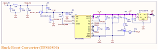
The system features two power sources. The first is a USB Type-C (5V3A max expected) for charging and sustaining backend system operations. The second source is a 3000 mAh 4.2 V Li-Po battery. Both power sources are integrated into the VIN of TPS63806 through a load sharing circuit consisting of a PMOS SI2301CDS-T1-GE3 and a Schottky diode SS34.

Selected ICs:

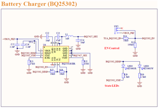
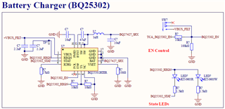
  • Battery Charger: BQ25302RTER
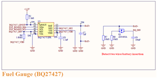
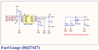
  • Fuel Gauge: BQ27427YZFR
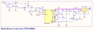
  • Buck-Boost Converter: TPS63806YFFR

Screenshot:

Additional Questions:

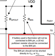
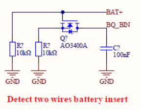
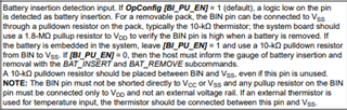
1. The BIN of BQ27427 requires a pull-up resistor(1.8 MΩ, As R6 in sch) connected to VDD (1.8 V). Since our battery setup does not include a thermistor, there is no pull-down resistor. Therefore, we designed an NMOS to simulate a ground resistor on the battery (refer to "Detect two wires battery insertion"). Is this design approach reasonable?

2. As I understand, when the battery is removed, the BQ25302 should not output any voltage, even though the device is enabled. Consequently, the LDO of BQ27427 cannot receive any power, implying that the I2C should not be operable. If maintaining the I2C connection for the BQ25302 is not feasible, is the circuit mentioned in question 1 necessary? Or can I determine the absence of the battery using an I2C timeout? Additionally, do you have any suggestions on how to keep the I2C of BQ25302 operational when the battery is removed but VBUS is present?

3. During normal operating modes, the anticipated supply current is < 0.7 A. Given that the wearable device also includes some PZT actuators, there might be current spikes lasting a few milliseconds (≤ 2.5 A). Is the system viable under these conditions?

Attache are the schematics for the power section, as well as those including the USB and microcontroller. I appreciate any feedback and thank you once again for your assistance.

Best regards,

Dennis

all_sch.pdfpower_sch.pdf

  • Update Screenshot:

  • Hi  Dennis,

    TSP63806 part is fine to me. just one question, since the output of LDO is 1.8V, why you set a 3.3V target output for TPS63806? is it better to set to a lower one?

    Regards

    Tao

  • Thank you for your review, Tao. Regarding your question, since I am using 3.3V (for most of the devices) elsewhere in the schematic, I have set the output to be 3.3V.

  • Hi   Dennis,

    Got it, thanks for your explanation. Froward this thread to BQ team, please  wait for their comments.

    Regards

    Tao

  • Hi Tao,

    thank you for the information and assistance.

    Regards

    Dennis

  • Hi Dennis, 

    I have reviewed the BQ25302 charger schematic and see no clear issues. All looks good.

    I have forwarded this thread to the gauge team to comment on BQ27427. 

    Best Regards,

    Garrett

  • Hi Garrett,

    I greatly appreciate your review, but I realized that I forgot to show in the schematic that PMID should be connected to V_IN (net label in TPS63806 region). Could you please help me confirm if this is correct?

    Additionally, I would like to know if you could assist me in confirming the second question in the Additional Question section?

    Thank you.

    Regards,

    Dennis.

  • Hi Dennis, 

    Please see my comments below. 

    What is the reasoning for connecting PMID to the output of the buck boost converter? From what I can understand it does not seem necessary. The input 'VBUS_FILT' net label is already shared between the buck boost converter and battery charger. PMID pin is also on the input side of the BQ25302, hence why I do not understand why it would be connected to output of buck boost converter. 

    2) Since you mention that no thermistor is used in your design if BQ25302 device is enabled it will provide power to output even if battery is removed. It will charge the output 10uF capacitor as if it is a really small battery. BQ25302 is a standalone charger. It does not have I2C communication. The rest of the question looks to apply to the BQ27427 gauge device. I will let the gauge team comment on it. 

    Best Regards,

    Garrett

  • Hello Dennis, 

    Please see the following comment from the BQ27427 regarding not using a battery pack thermistor. 

    Regards, 

    Jonny. 

  • Hi Garrett,

    Thank you for your response. Here are my comments:

    1. I think there might have been a misunderstanding. The PMID is connected to the input of the buck-boost converter and also where the load sharing circuit converges. The output of the buck-boost converter is labeled as +3.3V. Apologies for any confusion, as I am still a novice and my schematic might not be very clear. The reason I chose to connect the PMID to V_IN is based on Figure 9-6 of the BQ25302 datasheet, which shows that when there is an external power path (in this case, VBUS_FILT), PMID should connect to VSYS (here, it should be V_IN), and Q4 corresponds to T1, so PMID should be connected to V_IN.

    2. You mentioned an important concept: even though the BAT is not loaded onto the BQ25302 (actually, the battery is connected to BQ27427, then to BQ25302 via BQ27427_SRX), the SW of BQ25302 will still output a constant voltage and charge the capacitor. My understanding is that when BQ25302 is enabled, SW connects to BQ27427_SRX. According to Section 6.2's Function Block Diagram of BQ27427, SRX passes through a current sensing resistor to reach BAT. Can I interpret this to mean that BQ25302 will power the LDO when enabled?

    The reason I ask this is that I want to determine whether a battery is inserted, which can be achieved through hardware and software methods. However, I no longer have spare hardware pins available, and BQ27427 can read through the I2C interface the third bit of 0x06 to determine if the battery is inserted (by checking if the BIN pin is grounded). This is also why I am trying to implement a "Detect two wires battery insertion" feature.

    To achieve this, BQ27427 must maintain I2C operation even without a battery. According to the discussion BQ27441-G1: LDO not turning on/I2C not responding, I2C only responds when BQ27427's LDO is powered. Hence, the previous question about whether SW will output voltage without a battery load. Please let me know if there's any mistake in my explanation above. Thank you.

    Regards,
    Dennis

  • Hi Jonny, 

    Thank you for your reminder. However, I am hoping to implement automatic detection of the insertion and removal of a two-pin LiPo battery. Could you please review the second point in my previous response to see if it is reasonable? Thank you.

    Regards,

    Dennis

  • Hi Dennis, 

    1) Apologies I now see V_IN net label is the pullup for PG pin on buck boost rather than Vout rail. Thank you for the explanation. PMID is okay to be connected to V_IN. 

    2)When charging is enabled BQ25302 will attempt to charge whatever is connected at output to 4.2V. I will allow the gauge part expert Jonny to answer the parts of this question related to BQ27427.

    Best Regards,

    Garrett 

  • Hi Garrett, 

    Thank you for your review. I will be awaiting the response from Jonny.

    Best Regards,

    Dennis

  • Hello Dennis, 

    Can you please elaborate on your question, I am not fully sure what is being asked here? 

    Regards, 

    Jonny. 

  • Hi Jonny, 

    I have two questions:

    1. According to Garrett's description, if the battery charger IC is enabled, the SW pin will provide 4.2 V, and SW is connected to the BQ27427 SRX pin. SRX is internally connected to BAT+ through a current sensing resistor. If the battery is not connected, will the BQ27427 LDO still be activated? Will I2C work in this case?

    2. Can I simulate the action of inserting a battery with the following circuit? I hope that for a two-wire battery, the BQ27427 can still have the function of battery auto-detection insertion.

    Thank you in advance for your response.

    Regards,

    Dennis

  • Hello Dennis, 

    If a battery is not connected to the gauge, then the gauge will not be powered and the LDO will not be activated. If the gauge is not powered, then you will not be able to communicate with the gauge. Additionally note that this is a ROM gauge, so whenever the gauge is power cycled, you will need to have a host reconfigure the gauging parameters for the cell. For the battery auto insertion, please ensure that you are following the guidelines highlighted in the datasheet for the BIN pin. 

    Another option here could be to use the BAT_INSERT and BAT_REMOVE commands to indicate if a battery has been inserted or not. 

    Regards, 

    Jonny.