Other Parts Discussed in Thread: LM25148
Hello
I design LM25148 (LM25148QRGYRQ1) based DC/DC
Vin = 9-30V
Vout = 5V (6, 7.2 - options)
Iout(max) = 10A
Fsw=500 kHz, FPWM mode
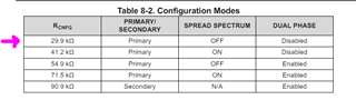
Primary, SSC On, Dual Phase Enabled (SYNCOUT Enabled)
External Compensation
Components was calculated using LM5149-LM25149 Quickstart Calculator_rev3.xlsm
Only one thing I missed. I mistaken with ext. compensation values. Recommended values for ~ 80 uF total Cout (soldered) are (6.34K+5n6)||68pF
(my values on schematic for 100uF, not 80uF). But I think it`s not critical for this issue.
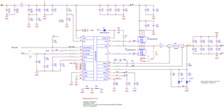
See schematic bellow.
Now I testing my design in lab. All work fine (Vout stability, efficiency) except one puzzle with Vout ripple waveform.
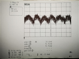
See screen dumps from my oscilloscope bellow, please.
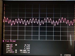
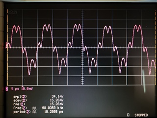
PIC_1. ~60 us (16 kHz) ripple
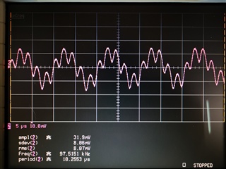
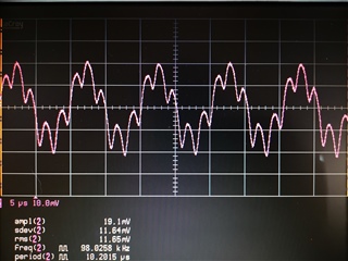
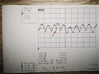
PIC_2. Zoomed x25 (500 kHz, Fsw)
My main question about "16kHz" ripple from pic.1
This ripple NOT changes with Vin (from 12 to 30V), Iout (from no load to 8A). Added 1000uF capacitance on Vout, Vin (after input LC- filter) is not change this ripple also.
Replacing laboratory power supply with battery, replacing DC electronic load with resistor and replacing probes in not help also.
Also I think this is not sub-harmonic oscillation (D always less then 50%)
In realty waveforms from screen dumps "breathe" and not stationary, modulation observed.
I suppose that "16kHz" ripple is a result of DRSS. Am I correct?
( also see red arrow on PIC_2. I think it`s phase change of LF part of DRSS)
Could anyone comment all described above, please?
-- Best Regards,
Victor
P.S.
Test setup
1. Laboratory power supply, battery
2. LeCroy DDA-125 (aka LC-684)
3. LeCroy AP020 active probes.
4. -3dB Custom probe: 50R ---> RG174---> DC block --> DDA125 (50 Ohm input)
5. TTi LD300 (DC Electronic load)