This thread has been locked.

If you have a related question, please click the "Ask a related question" button in the top right corner. The newly created question will be automatically linked to this question.

UCC28C53-Q1: RVDD Configuration

Part Number: UCC28C53-Q1

Dear Team,

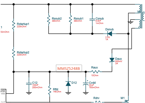
I am designing the flyback the with Vin 67 to 180rms, and Vo 12V, 2A. I have gone thru the Webench schematic, observed that 18V zener connected across VDD pin for protecting the IC.

the D12 is VZ 18V @ IZT 7mA, now the doubt is the since total RVDD are 440K,  it allows 0.21mA at 67V rms. it should allow the 7mA+70uA to IC get start puls right ? how does 0.21mA helps ? Pls explain 

  • Manoj,

    The startup resistor are sized so that at least 75μA (minimum startup current needed) is available at minimum input voltage. Rstart=[67V*SQRT(2)-UVLO_ON]/75μA=(94.75V-9V)/75μA=1.1MΩ. Your design shows Rstart=440kΩ which is 195μA and this is 2.6x the minimum needed, so the startup resistors are sized correctly.

    When VDD crosses the UVLO_ON threshold, switching begins and the VDD level begins decreasing until UVLO_OFF. The CVDD capacitor holds up VDD until the bootstrap voltage takes over. Since VDD only reaches UVLO_ON and then start to decrease until the bootstrap winding takes over, D12 should not be conducting during startup. Once the main output is regulating, the bootstrap winding will cross regulate to the main winding. D12 will only conduct id VDD tries to increase during a transient or maybe light/no load condition. If/when D12 conduct, this will be during steady state operation and will have no effect on stealing startup current needed to get the PWM started.

    Regards,

    Steve