Hi,
The ouput is not ragulating
please help me to solve this problem
vout (set)=24v
Iout=27A
VIN 400v
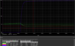
Here the output resistance is 2R and output voltage drops to 22v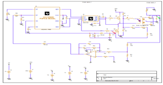
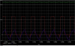
Red : gate-source voltage
blue : Drain current
Geen : output voltage
Hi,
The ouput is not ragulating
please help me to solve this problem
vout (set)=24v
Iout=27A
VIN 400v
Here the output resistance is 2R and output voltage drops to 22v
Red : gate-source voltage
blue : Drain current
Geen : output voltage

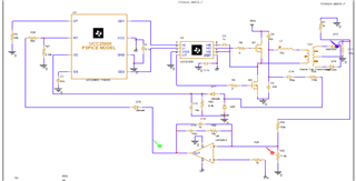
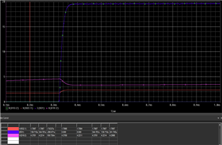 here is the output voltage of error amp(pink color waveform )
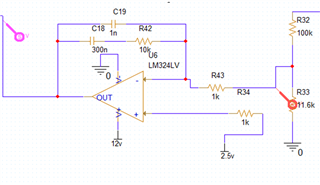 Here is the schematic diagram of feedback loop