This thread has been locked.

If you have a related question, please click the "Ask a related question" button in the top right corner. The newly created question will be automatically linked to this question.

LMR16030: Switching Frequency Wrong

Part Number: LMR16030

I am using this regulator for a project, and the switching frequency is extremely low. The ripple is also terrible, although this is likely a symptom of the lower-than-expected switching frequency.

We get +4.7 V out, so it is regulating properly. Here are some screenshots with different loads. Rt is 56 kO, which should correspond to a switching frequency of about 450 kHz. I measured Rt on the PCB, and it is the correct value. I also ensured that it is properly soldered. Again, it is correct. Here are some oscilloscope screenshots with different loads.

This is with a 49 O load, which means that the load current would be about 97 mA, which is not huge. I will point out that the switching frequency is 303 Hz, and the ripple is 6.7 V.

________________________________________________________________________________
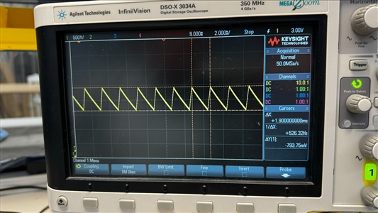
This is with a 204 O load, which means that the load current would be about 23 mA, which is not huge. I will point out that the switching frequency is 526 Hz.

________________________________________________________________________________
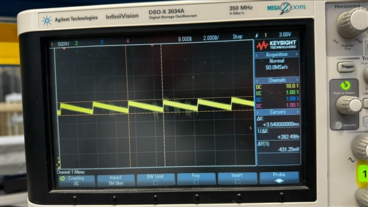
This is with an open load. The switching frequency is 282 Hz.

This is not an enormously complicated regulator, and there's only so much that could go wrong. Since the regulator is regulating, it's probably not damaged, but I've never seen this kind of issue before.

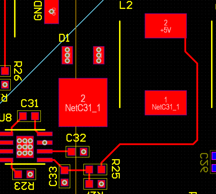
Here is the layout. Note that I've hidden planes for the sake of clarity.
  • Hi Alexander,

    The part has "sleep mode" when the load is light to achieve high efficiency. If you increase the load to 2A, for example, the switching frequency should be at 450kHz.

    Ben

  • Hi Ben,

    That makes sense, but then there is still the issue of the ripple. If you look at the first two screenshots, the voltage ripple at the output is 6.7 V and 793 mV. In practice, this regulator will always see a load. Among other things, it powers a display, a microcontroller, and a 3.3 V buck converter.

    We noticed that it would cause the buck converter to burn, the +8V peak in the first screenshot could be enough to damage it.104 uF should be tonnes of output capacitance, and 100 uH should be enough inductance to make the current ripple negligible.

  • Hi Alexander,

    I would check to see if the loop is stable. If you increase the load so you are not in sleep mode, what is the ripple on the output? Can you measure the inductor current via current probe? Have you tried WEBENCH? I see that you are using a 100uH inductor. That is quite high since the datasheet application uses an 8.2uH for a switching frequency of 500kHz.

    Ben

  • 100 mA should bring us out of sleep mode, and the ripple was 6.7 V (see my first screenshot). I was wondering if the inductor was causing the problem myself. I ran another test at a moderate load (50 mA or so), and there was a low frequency triangle wave (300 Hz), but on the rising side of the triangle wave, there were high frequency impulses at 438 kHz, which is pretty close to the switching frequency.

  • Hi Alexander,

    It has to be above 300mA, as stated in the datasheet.

    Too high of an inductor will make the part act more like a voltage mode than a current mode control part. Try lowering the inductance to a 8.2uH and retest your conditions.

    Ben  

  • Hi Ben,

    Full disclaimer: we use this chip twice, once for a +5V regulator, and once for a +12V regulator. Apart from the feedback resistors, the topologies are the same. They were both exhibiting the same anomalous behavior.

    Now that that is out of the way, I happened to have an 8.2 uH inductor with the same footprint, so I replaced it. The issue was certainly less pronounced, but it didn't disappear (screenshots to follow).An E-Load is the best tool to test this, but I forgot to bring my personal one to work today, so I had to use a potentiometer.

    This was with a load current of about 40 mA.

    The load current here was 460 mA, so this should be out of sleep mode.

    In both of these cases, the inductor was screaming like a banshee.

  • Hi Alexander,

    The switching frequency for the load current of 460mA is 2.1kHz, which is much slower than 450kHz. Can you tell me the purpose of capacitor C33? Try removing that cap and retest.

    Ben 

  • The problem was C33. I removed it, and everything was better.

  • HI Alexander,

    Awesome! Glad to hear that everything is better.

    If there are no further questions, can you click on "resolved" to close the thread? Good luck to you!

    Ben