This thread has been locked.

If you have a related question, please click the "Ask a related question" button in the top right corner. The newly created question will be automatically linked to this question.

LM61480-Q1: Schematics Design

Part Number: LM61480-Q1

Hi TI Team,

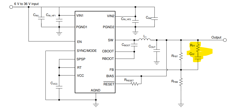
For LM61480QRPHRQ1, in the typical application diagram in the datasheet, RFF and CFF are placed as shown below.

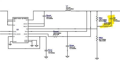
But while doing the simulation for these part, the RFF and CFF caps are placed different

Could you please confirm which to follow?

  • Hello,

    The resistor and capacitor are in series with each other and parallel to the top feedback resistor. It does not matter the order of components just that it is connected in this arrangement (across the feedback top resistor).

    Regards,

    Jimmy