This thread has been locked.

If you have a related question, please click the "Ask a related question" button in the top right corner. The newly created question will be automatically linked to this question.

LM25184: LM25184NGUR

Part Number: LM25184

Hello TI Team,

We are implementing a DC-DC converter where our input voltage is 34 Volts and we are trying to get dual output of +22V and -6V. We are using the excel sheet given by the TI for LM25184. 


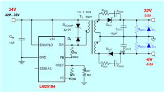
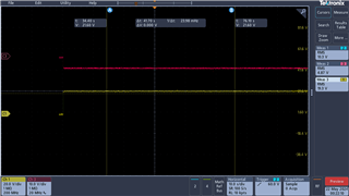
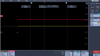
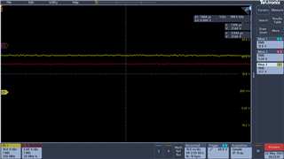
Our transformer is a customer designed transformer with 1:5:1:0.278 +-3%. Currently the output voltage we are getting is +32V and -8.45V. It looks like there is a feedback problem, but I have checked with different resistances but still getting the same voltages. The design sheet is also attached here for the selected requirements. Can you please have a look and let me know what can be done to get the right voltages. Thanks

LM25184 DESIGN FILE.xlsx

  • Hi Mubashir,

    Thank you for designing with the LM25184.  I don't see obvious problem in your calculator.  Did you apply any load to the output?  There is a min load requirement which can be fulfilled by either the dummy load Rdmy in our calculator schematic and/or Vout Zener clamp.

    If your circuit meets the min load requirement, and you still see over voltage, please share the following info:

    • Your own version of the schematic that  you used to design your PCB.  Please make sure all component values are accurately labeled. If some parts in the schematic are not used, please also indicate.
    • Your transformer datasheet.
    • Your load condition when observing the over voltage in the output.

    Best Regards,

    Youhao

  • Hello Youhao,

    Thanks for your fast reply. You are right, I didn't put the dummy load as I had another load but currently its not populated on the board. The reason for not putting dummy load was according to calculator, it was optional. But, I will put a dummy load.

    However, does this means that even you are putting another IC as a load to LM25184, do you still need this dummy load for startup??

    Also, please keep this thread open, when I will get the over voltage, I will provide you the information you requested. However, as there is snubber circuit with both outputs, I am not expecting an overshoot, what do you reckon?

    Thanks for your help, mate.

  • Hi Mubashir,

    Sorry for the confusion. The dummy load is to keep the output voltage at the regulation level when your actual loads become very light or even no load. When you have another IC as the load, it should meet the min load requirement, or additional dummy load is still needed to prevent Vout from going higher.  When you see 32V, it indicates that you did not install the Zener, either, right?  You may save the dummy load resistor if you install the Zener.  Of course you can use both of them.

    The snubber circuit is to suppress the peak voltage ringing across the diode. If the snubber is selected properly, the ringing will be much damped.

    Thanks,

    Youhao

  • Thanks mate for your fast reply. I will let you know how it goes. Thanks

  • I am looking forward to your updates.  Please post after you have results.

  • So, I got my desired voltages. I checked the ringing in output but there is no ringing found. So, there are three results attached. Image 0004 & 05 showing both +22V & -6 V while image 0006 showing the ripple in voltages.

  • P.S : Its starting from zero as I turned on the power supply suddenly to see any overshoot in the output voltages.

  • Hi Mubashir,

    Thank you for the updates.  It seems the issue is resolved, right? 

    Best Regards,

    Youhao

  • Yes, the issue is resolved.