UCC28C56H-Q1: HV_IN power supply minimum starting voltage and secondary side regulation (SSR) circuit modification for Vout=12V

Part Number: UCC28C56H-Q1
Other Parts Discussed in Thread: UCC28C56EVM-066

HI Team, I have two question about UCC28C56EVM-066 board:
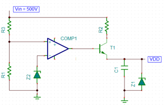
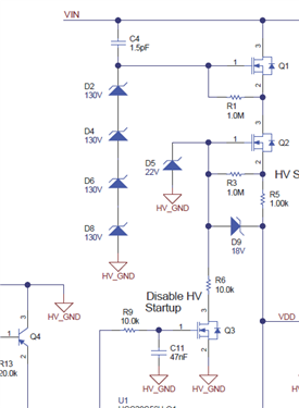
1) In the EVM, the 15Vdc Vout start form 40V of HV_IN power supply. Is possible to modify the EVM for start Vout (15Vdc) from 500V of HV_IN power supply?
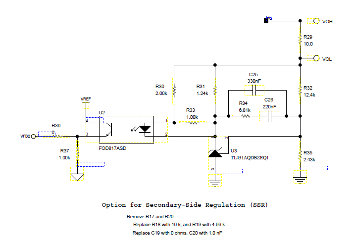
2) On UCC28C56EVM-066 board I have implemented the isolation circuit for secondary side regulation (SSR) shown below. Is possible modify this circuit for have a Vout=12Vdc?
Thank you.

Best regards

Bruno.

  • Hi,

    1) you can change the design startup to a resistor startup, tie a resistor from VDD pin to Vin, design the resistor value so only 500V can produce typical 50uA into VDD pin. Note you may need to make that resistor into several in series connection to sustain 500V or higher voltage. Also note, the VDD startup current has a range, between 29uA and 75uA, so only using the IC VDD turn on threshold, you wont get precise turn on at 500V. If you need a precise 500V turn on, you would need to add external turn on circuit such as a voltage comparator.

    2) You need to design R32 and R35 to make U3 2.5V at its pin 2 when Vout = 12V. 

  • Hi, thank you for your quick answer.
    1) Can you suggest me a IC solution for a precise 500V turn on?
    2) I have tried to change R32 and R35 values for a Vout=12V but this solution work correctly if I remouve also R33. That is che function of R33? It's correct remouve it?

  • Hi,

    1) You can use any voltage comparator but need the circuit like below. When Vin = 500V, COMP1 output = high to turn on T1 then Vin through R2 and T1 charge up C1 to reach VDD UVLO on then the IC turns on. Design R2 allow the current > 100uA when T1 is on.

    2) You can remove R33. Usually R33 and R31 one of them should be good enough. Either one has one function to establish some bias the opto coupler diode so the diode is not completely off which can help transient.

  • Hi,

    Is possible modify the HV startup circuit present on UCC28C56EVM-066 EVM board (shown in the picture below) for work like a comparator?

  • Hi,

    You can use the voltage comparator circuit to turn on Q3 until Vin reaches 500V then disable the voltage comparator and back to Q3 original control. It does not seem worth modifying the original HV circuit on the EVM since you still need to add the comparator circuit to get the precise Vin turn on point. The HV circuit on the EVM cannot provide precise turn on threshold so a voltage comparator to decide when Vin reaches 500V is still required. So you would need more cost and more components if just add more components on to the HV circuit while it can save a lot with a new circuit.

  • Hi,

    OK thank you.
    And if I could accept an activation that is not precise but close to 500V, is it possible to modify the circuit by not using the voltage comparator?

    Regards.

  • Hi,

    The start up current is between 29uA and 75uA so you will design with one number then check the range of the input voltage. Then it would be ok you can  accept that range of the input to start - then you do not need to use the comparator.