Other Parts Discussed in Thread: TL431
Hello Ti,
As the title says, the converter I'm working on (HIGH VOLTAGE Flyback DC-DC Converter) doesn't stop regulating when the output load reaches a chosen Iocc value.
Target values:
- Vin = 60 - 1000V
- Vout = 100V @ Iout = 0.1A (Rload = 1k)
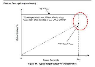
- Iocc = 0.16A @ Vocc = 80V (Rload = 500 ohm)
- Vov = 120 V
The values I need to work with for the transformer (I can't change them):
- Np = 36, Na = 12, Ns = 64
- Nps = 0.5625, Npa = 3, Nas = 0.1875
- Lp = 1.07mH (measured with RLC meter)
I managed to calculate the values of the components using the formulas in the datasheet, EXCEL provided by you ("sluc652b") to make sure I got the values right, and using the Simplis model provided.
Initially, my target frequency was fmax_target = 67kHz, but following a personal mistake (I chose the wrong transformer core, instead of being gapped, it is gapless), I increased the inductance in the primary from Lp_target = ~300uH to Lp_actual = 1.07uH. I think the actual maximum frequency at which the converter can operate is fmax_real = ~20kHz (based on what the sluc652b EXCEL says).
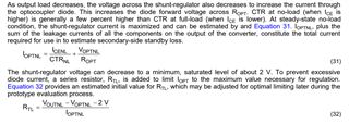
Also, the values for R_TL and R_opt are chosen by trial and error, since initially the converter did not work with the values from EXCEL. Also, I didn't change the values for R_fb3, R_fb4 and C_fb because I didn't know what values I should put in their place.
I'll attach some screenshots from the simulator with a normal load, and one where I exceed the Iocc threshold (Rload = 100 ohm) + the EXCEL I used to calculate those values.
I kindly ask you from the bottom of my heart to help me solve the problem if possible.
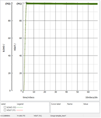
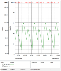
Rload = 1k (the converter works even with 50k or 100k load)
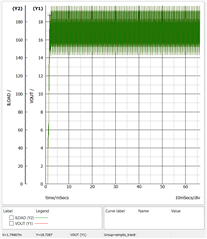
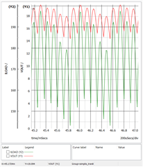
Rload = 100 ohms (it is not working even with 1ohm).
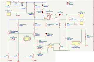
Schematic
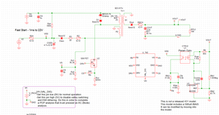
Kicad schematic
sluc652b_flyback_High_voltage.xlsx
Best regards,
Alexandru