TPS2H160-Q1: Issue with EN Pin Functionality on Load Switch for 3A Load

Part Number: TPS2H160-Q1
Other Parts Discussed in Thread: TPS2H160EVM, TPS1HTC30-Q1,

Hi team,

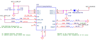
When testing the load switch, we observed the following behaviors under different conditions:

  1. EN Pin HIGH or LOW:
    • When the EN pin is set to HIGH, the switch behaves as expected, allowing current to flow.
    • When the EN pin is set to LOW, the switch also behaves as expected, preventing current flow.
  2. EN Pin LOW and DIAG_EN Pin HIGH:
    • When the EN pin is LOW and the DIAG_EN (Diagnostic Enable) pin is HIGH, the switch unexpectedly allows current to flow, providing an output. This is not the desired behavior.

It appears that the DIAG_EN pin is functioning as a default enable pin, overriding the state of the EN pin under certain conditions. This behavior was not anticipated based on the standard operation mode described in the documentation.

case1 ENABLE 0 0V
LATCH 0
FAULT 0
DIAG_EN 0
case2 ENABLE 1 8V
LATCH 0
FAULT 0
DIAG_EN 0
case3 ENABLE 0 8V
LATCH 0
FAULT 0
DIAG_EN 1
case4 ENABLE 0 8V
LATCH 1
FAULT 1
DIAG_EN 1

This condition completely contradicts of what we desired to use this in our case.

  • Edit- For the case 3, the output is 0V

  • Athiamaan,

    Are you testing this on an evaluation module or your actual board? DIAG_EN simply controls whether diagnostics are reported on the SNS/FLT pin and should not have any interaction with the device itself.

    Do you have a scope shot of the EN/DIAG_EN/VS/OUT pin to look at?

    Best Regards,
    Tim

  • Hi Tim,

    We are testing a 3A load switch on our actual board but encountered issues with the EN pin functionality. To troubleshoot, we recreated the circuit on a practice board to isolate it from other elements.

    And here is the schematic that we used the load switch for switching.

    regards,

    Athiamaan

  • Athiamaan,

    Given the appearance of the soldering/board on the picture, I would highly recommend re-running this test using the TPS2H160EVM. I suspect there might be a short/issue with the soldering here which is causing unexpected behavior and using a known EVM board would eliminate the doubt here. Let me know if you need one and I can get a sample sent to you.

    Best Regards,
    Tim

  • Athiamaan,

    Just to clarify here- are you using TPS2H160-Q1 as the title to this post indicates, or TPS1HTC30-Q1 as referenced in you schematic?

    TPS1HTC30-Q1 has an integrated pull-up from VOUT to VBB that is used for open load detection in the OFF state. This pull-up is enabled via the DIAG_EN pin and would explain the behavior you are seeing. The TPS2H160-Q1, however, does not have this internal pull-up and would not show this behavior (which is why suggestion was to make sure the soldering connections were good).

    Best Regards,
    Tim