This thread has been locked.

If you have a related question, please click the "Ask a related question" button in the top right corner. The newly created question will be automatically linked to this question.

LM7481: Voltage spikes causing board issues

Part Number: LM7481

Tool/software:

Good Morning - 

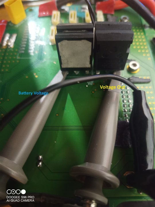
I am having an issue with the LM7481 circuit on one of my boards. My current set up is as shown in the schematic and images below:


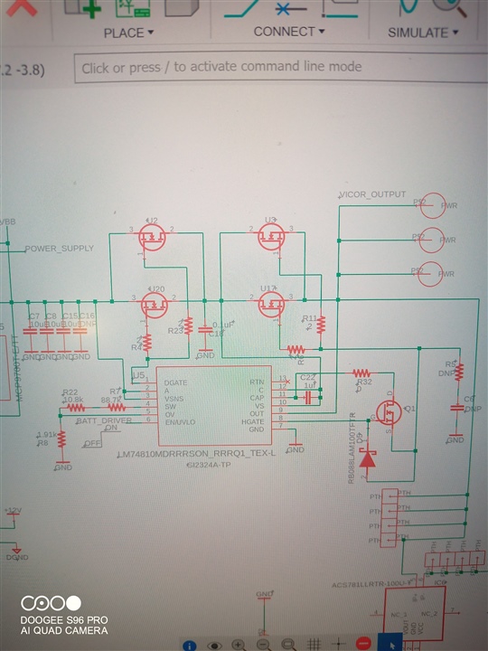
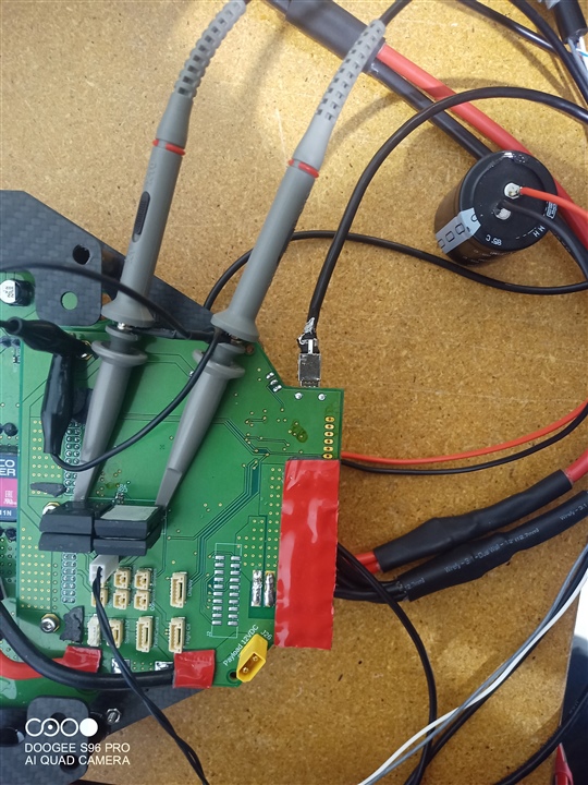
The schematic shows an LM7481 with common drain topology and includes the transistor/diode setup on HGATE to allow for faster FET switching. I am using the LM7481 to switch between main power and battery power.  The system needs to charge 4800uF of capacitance on start up to allow the Vicors to come on (they don't start up well into capacitance). On start up of the system, we switch on the battery FETs shown above for 2 seconds to fully charge the capacitors and stabilize, then switch over to Vicor power (another LM7481 setup).  This is the output that I get:


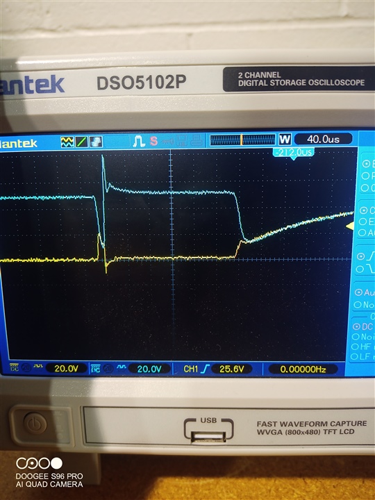
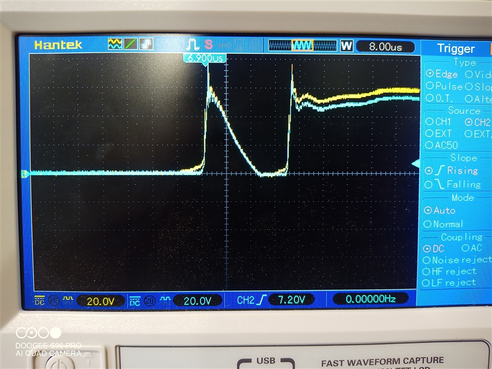
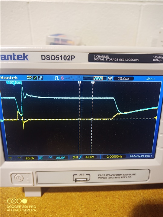
(Yellow is the output to the capacitance that is being charge and Blue is the battery/Common drain voltage)

It almost looks like the LM7481 initially turns on which pulls the battery voltage down due to the inrush current to the capacitor, but then abrubtly turns off (where the negative spike on the output and 80V spike on the Battery/drains. After a small settling period, it looks like it tries it again and does what I would expect from it. It switches on in a few microseconds and then has a decent capacitor charging curve that I would expect. 

The negative transient on the output makes me nervous and so does the 80V voltage transient.  This image is with added parts that are not in the schematic - added a schottky diode on the output to take care of negative transients and a 56V zener diode on the drain to see if that would help the 80V transient. Neither of those additions appear to be helping, but now it is preventing the chip from exploding and then backfeeding into the MCU and taking the MCU out too. 

Just looking for direction on how to fix the issue and things to try to get rid of the transients. 

Thanks for all the help!!!

  • Hi Andrew,

    4800uF with a stronger drive seems very huge and inrush will be very high. Chances are that VIN will hit UVLO. Did you try with an inrush limiter? This for sure will slow down the turn on, but just to eliminate any issues related to controller and schematic can you try this once? By using R5 and C6.

    Regards,

    Shiven Dhir

  • I will get a reading of the digital output from the MCU to my enable line and see if the input is getting dragged down below V(enf). I will then attempt to use the snubber circuit to slow down the gate on timing. Unfortunately, we are driving 60 amps Max with this. We need the switch on time to be pretty fast so that the parallel mosfets stay within their SOA. May need to find a happy medium between keeping it in the SOA and slowing down for inrush current. 

    I'll post pictures here soon thank you for the all the help. 

  • So did some more testing and found that when I set my oscilloscope to 8uS scale, and remove all of the 4800uF capacitance on the output so no load, I get these waveforms which are very similar to what is seen in the other one - like it tries to turn on and then shuts off and tries turning on again. Do you know of any internal operation that could stop it from turning on fully the first time?

  • Hi Andrew,

    Can you please label the channels for me?

    Yellow -VOUT

    Blue - Common drain.

    Right?

    Shiven Dhir

  • For this one the yellow is the Vout and blue was the gate of the FET. I wanted to check for ringing which was visible on here. I increased the gate resistors to 10 ohms and it got rid of the ringing but my wave form still looks like the original waveform at the top.  

  • Hi Andrew,

    Can you also capture VIN while this is happening? Looks like VIN profile is bad.

    GATE signal is DGATE or HGATE?

    Regards

    Shiven Dhir

  • Yes I will here in about 2 hours. VIN is a lithium polymer battery. It follows pretty close to that blue line on the original images of the oscilloscope. I will post soon. 

    Gate signal was HGATE. 

    Thank you for the quick responses. I will get you more scope shots soon. 

  • Out of curiosity - blue being battery and yellow being VOUT - this looks like battery (VIN) dips below VOUT. I assume that would cause a reverse current and maybe that is why it is shutting off abruptly? Then sudden shut off would cause positive transient on the input and negative transient on the output due to line inductance/capacitance? If that were the case then I don't understand why is happens just fine the second time it attempts turning it on but just throwing ideas out there on my way to work.