LM5146: sync fly buck converter Ic heating

Part Number: LM5146

Tool/software:

Hey!

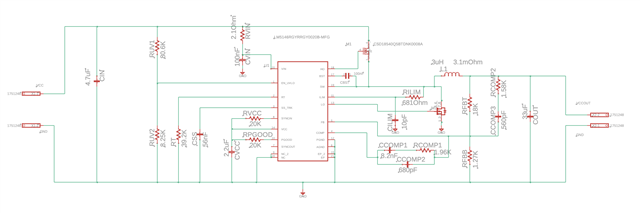
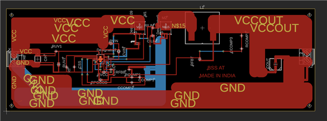
We at bss-at (https://bss-at.com/) are building power supply for input 14v to 60 volts and outout 12 volts. The circuit used by us was exported from TI power designer (webench.ti.com/.../switching-regulator) using LM5146. Please, note all parts used have exactly same value as provided by the power designer tool.

Currently the issue which we are facing is LM5146 is heating whenever we are providing voltage more than 16 volts. Below 16 volts the output of the power supply is 4.8 volts.
Please, suggest how to resolve this issue. We are attaching pcb and circuit screen shots.

  • Please, not value of M2 connected to LO is CSD18512Q5BTDNK0008A

  • Hello Arna

    The layout should be improved to make the device work properly. Please refer the layout example at https://www.ti.com/lit/ug/snvu545a/snvu545a.pdf . Also it is recommended to use >=4-layer PCB. 

    • Need a large AGND copper island
    • Locate RUV2, RT, CSS, CCOMP1, RCOMP1, CCOMP2, RFBB close to the IC
    • Locate CBST, CVCC, CVIN close to the IC
    • Need a large ground copper area on the bottom side
    • RLIM should be directly connected to M1 drain
    • Locate M1, M2 close to the IC
    • Route the HO-SW pin traces in parallel
    • Route the LO-PGND traces in parallel
    • Make the SW node area small
    • Connect M1 and M2 using a wide trace

    -EL

  • Hello Eric,

    Thank you for quick reply. We will improve the layout and redisgn the pcb keeping all points in mind.
    But right now the major issue we are facing is validation of this circuit.
    Even on 16 volts input the output is 4.8 volts and no heating.
    If voltage is more than 16 volts LM5146 is heating without any load and output voltage is 2 volts.
    Should we proceed with pcb designing of the same circuit?

    Regards,
    Team BSS

  • Hello Arnav

    Yes, please re-design PCB with the same circuit. I actually suggest you to follow these design steps #1 buy the LM5146 EVM, #2 modify the EVM match with your circuit design, #3 verify your circuit design, #4 design PCB, #5 populate the components based on the verified circuit design. 

    -EL

  • Hello Eric

    Sure will explore more regarding LM5146-Q1 EVM. But we still have one doubt why on 16 volts input the output is 4.8 volts and not 12 volts ?

    Regards,
    Team bss

  • Hello Arnav

    It can be caused by many reasons since the PCB layout is not properly designed. For example, if the analog ground connection  is not good, then the system might be unstable or an accurate VOUT feedback is not possible.  If the VCC cap is placed away from the IC, it can cause an IC malfunction.......

    -EL 

  • Hey Eric!

    Thank you for your support. We have modified the pcb according to you suggestions and were able to get 12 volt output. But if we increase output load the voltage starts droping. Is there anything we should do?

    Regards,
    Team bss

  • Hello Arnav

    How much drop is there ? <1% drop might be caused by DC gain of the loop response, which is natural. 

    If more than 1%, it should be caused by PCB layout / component locations.

    The high-side feedback resistor should be connected to the point which you measure the VOUT (+)

    The low-side feedback resistor should be  directly connected to the AGND pin. 

    The DC offset between the AGND pin and the point which you measure VOUT(-) should be close to zero.

    -EL