TPS55288-Q1: output current limit behavior

Part Number: TPS55288-Q1
Other Parts Discussed in Thread: TPS55288

Tool/software:

Hi Team,

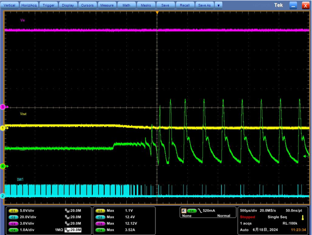
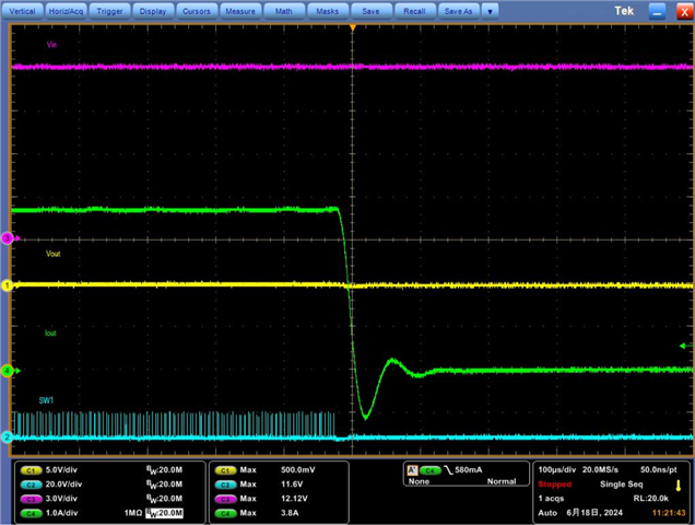
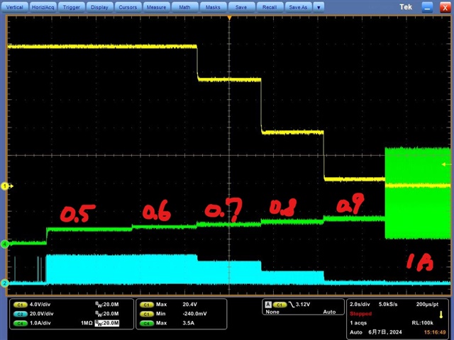
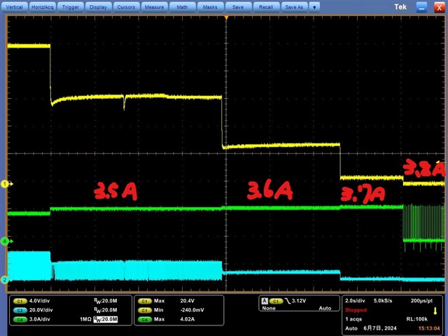
Could you help to check attached waveform? Output voltage drop when we increase load current.

Please let me know which portion I need to check first to figure out the issue. Thanks

10mV/ Boost

40mV/ boost 

Ben

  • Hi Ben,

    Thanks for reaching out. May I know what is the customer and the application here?

    1. Can you share the schematic and layout here?

    2. Can you also add the SW1 waveform in the above test results? And zoom in the waveforms of 0.9A->1.0A, and 3.7A->3.8A?

    3. As I know, PD3.1 spec shows currentt PPS doesn't need to support Vout smaller than 5V, why does the customer test this?

    4. Please check the Vstart voltage of the e-load, when Vout is very small, the e-load may shutdown.

    BRs,
    Bryce

  • Hi Bryce,

    Attachment is schematic and layout for your reference. For item4, we have check it not e-load issue. FYI

    GE_METEOR LAKE_A1_20240205 TPS55288.pdfGEHC_Venue_MPB_Board-0A10-0129.zip

    We found SW1 is switching during boost mode in below condition.

    0.9 to 1A (ISN-ISP=10mV, Rsense=10mohm)

    3.7 to 3.8A(ISN-ISP=40mV, Rsense=10mohm)

    Regards,

    Ben

  • Hi Bryce,

    We also want to know why SW1 switching when device operate in buck mode and trigger to OCP.


    Regards,

    Ben

  • Hi Ben,

    Thanks for the waveforms.

    As I mentioned, PD3.1 spec shows current PPS doesn't need to support Vout smaller than 5V, why does the customer test this?

    And from the waveforms, the Vout is very low close to zero, FYI, the minimum recommended output voltage by TPS55288 is 0.8V.

    BRs,

    Bryce

  • Hi Bryce,

    Customer's application is 12Vin to 20Vout. And they want to know why output drop step by step (as picture in first post) even Iout not trigger to current limit.

    They don't really care about PD3.1 spec or Vout close to 0V.

    I found there are two different current limit, output current limit and average inductor current limit. Does this two both are cycle by cycle current limit? And the protection behavior is limited duty cycle and will cause output drop?

    If yes, I think we need to focus on current limit accuracy.

    If not, please show how this OC protection work.

    Regards,

    Ben

  • Hi Ben,

    Thanks for feedback, can the customer show the waveforms of inductor current, SW1, SW2, and Vout when Iout changes from 0.6A->0.7A, 3.4A->3.5A and Vout drops?

    The output current limit and average inductor current limit are regulated by internal current loop, the output current or average inductor current is limited at the set value when the protection is triggered, thus output voltage would drop.

    BRs,

    Bryce