BQ76942: BMS with replaceable batteries - concerns about floating ground

Part Number: BQ76942

Tool/software:

Hi, our design uses the BQ76942 to manage a 7S LiFePO battery pack. 

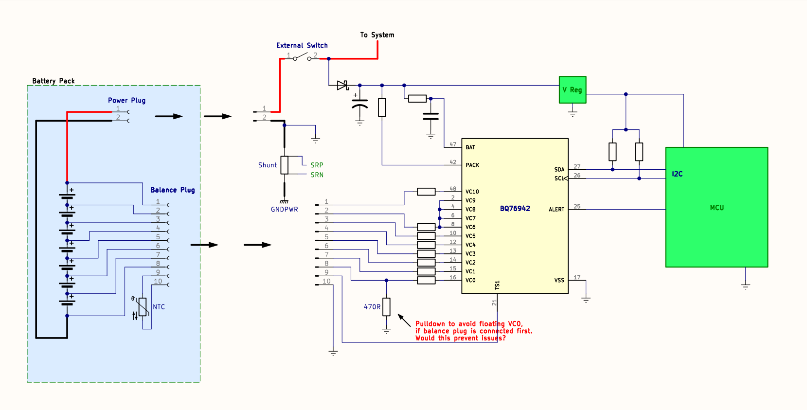
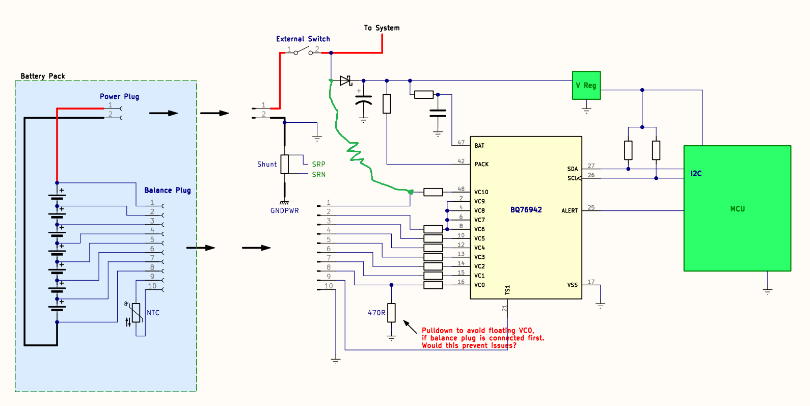
The BQ76942 is on the product's PCB, while the battery pack (simply bare cells and a thermistor) can be removed and replaced. It is connected to the PCB by 2 plugs:

  1. A 2-pin POWER plug for carrying battery current, and
  2. A 10-pin BALANCE plug for connecting each cell to the BQ76942 (and also thermistor).

Here's the issue. As you can see in the simplified schematic below, if the BALANCE plug is plugged in before the POWER plug, the PCB's ground net is not yet connected to BAT-.

This means that VC0, VC1, VC2, etc, would be connected to battery cell voltages while the BQ76942 has a floating/undefined value at VSS.

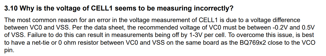
The datasheet states that random cell attachment is only supported if voltage at VC0 is kept close to VSS. If the BALANCE plug is connected before the POWER plug, this condition will be violated.

To avoid this, I added the 470R resistor shown below. I added a resistor (rather than a 0R jumper or net tie) because I was concerned about connecting to ground in 2 places (once the POWER plug is connected), creating a ground loop.

My question: is this a good solution? We've had some failures on prototypes of the below circuit (with the 470R resistor). The BQ76942 stops responding over I2C, so it seems to be dead, and we don't know what is causing this. Should the resistor instead be a 0R jumper (i.e. are my ground loop concerns not an issue?), or does the existing setup look fine and the failures are caused by something else?

Any other feedback/suggestions for this design is welcome. Thank you.

  • Hello,

    You can try a 0Ω resistor and see if that helps it. It would be best to connect the power plug first then the balance plug.

    Best regards,

    Thomas Rainey

  • I know it would be best to connect the power plug first, but this design needs to be robust, as end users can't be controlled.

    I will try with 0R resistor. Do you think there could be any issue with connecting to ground at two points? (through 0R resistor and through power plug). I know from experience this can pick up emf in audio applications, but would it be fine here? 

    Thanks.

  • In the BQ769x2 FAQ document it says this:

    Wouldn't a net-tie or 0 ohm resistor between VC0 and VSS short out the balancing resistor? Or is this supposed to mean connect the net-tie/resistor AFTER the balancing resistor, to VSS?

  • Hello,

    Connecting two points to ground shouldn't be a problem. 

    The the 0Ω resistor should not short out the cell balancing resistor. Current flowing from the VC0 pin to the cell balancing resistor then to ground.

    You will need to test in your configuration to confirm.

    Best regards,

    Thomas Rainey

  • Drawing the proposed 0R resistor onto your diagram above shows that it WILL short out the VC0 balancing resistor, unless I'm misunderstanding something? 

  • Hello Oscar,

    The 0-Ohm resistor would not be at the VC0 pin directly, it would be right after the balancing resistor, in a location similar to your 470-Ohm resistor.

    The main concern about what you're trying to do is that the VC0 pin is a low-voltage pin, so it can more easily be damaged than other pins. The 0-Ohm would ensure it remains close to Vss.

    Now, something I just thought about. You need to have VC10 connected to the same node as the BAT pin when the part is initially powered. VC10 is used for the Top-of-stack voltage measurements, by default if the measured voltage is below 6-V, the part will go into SHUTDOWN. This may happen if you power the BAT pin first and leave VC10 floating.

    Our monitors are typically meant to be inside a battery pack, so although your configuration may work, there may need some additional work to get it all figured out.

    Best Regards,

    Luis Hernandez Salomon

  • Thanks for the quick response. Understood, I will just change the 470R resistor to 0R. It may be worth changing the the FAQ document section shown above, as the wording clearly states "0 ohm resistor between VC0 and VSS." 

    As for your other observation, thank you. After connecting battery, the BQ76942 in our prototypes needs a pulse on the RST line before it will accept I2C. This must be because it is in soft shutdown mode (TS2 is tied low) due to the condition you describe, and so it needs partial reset to exit it from soft shutdown.

    For a solution, what if I add a resistor / net-tie from VC10 (after the balancing resistor) to BAT (before the hold-up circuit), so that VC10 is high whenever the part is powered, even when the balance plug isn't connected yet? i.e. the connection drawn in green below:

    I can't think of any problems this would cause, considering the random cell attachment tolerance of the device.

    The cells will only be replaced once or twice during the lifetime of the product, so most of the time it will be like the BQ76942 is inside a battery pack.

    Interested to hear your thoughts, thank you.

  • Hello,

    Yes you are correct. That may need to be reworded. I will let the author know and they will make note.

    Adding that resistor/net-tie should work.

    Best regards,

    Thomas Rainey