This thread has been locked.

If you have a related question, please click the "Ask a related question" button in the top right corner. The newly created question will be automatically linked to this question.

BQ25798: BQ25798RQMR

Part Number: BQ25798

Tool/software:

1).  Issue and Symtom :  During charging, the current increases and then Stop the fast charging.

   ⓐ  Charging start : CE High to Low. Charging status of Register is indicate Fast charging.

   ⓑ  IBAT register shows always 0mA ( after set 80h of Index 2Eh ), but low current charging is continuing.

   ⓒ  Charging Current was ramp-up rapidly(around 2.3mA) at battery voltage 15~15.1V after that, stop Fast charging

        ( refer to below figure1 of page 1)

2) Test enviroment

    - Battery Pack  : Li-ion 4s1p, Fast Charging (0.5C), Discharging current (1C typ, 2c max)

                          Output Voltage (14.4V typ), Charging Voltage(16.8V)

                          Cutoff discharging voltage(11.2V), Recover Voltage(12V)

3) Requtst:  Please give me advice on solving problems in circuit or PCB design.

  • Hi Hee,

    Charging Current was ramp-up rapidly(around 2.3mA) at battery voltage 15~15.1V after that, stop Fast charging

    What is the charge voltage? Can you provide the register values when this occurs?

    low current charging is continuing.

    Can you clarify on "low current"? 

    ( refer to below figure1 of page 1)

    From my view there is nothing attached. 

    Best Regards,

    Jibin 

  • charger area image_20240702.pptxcharger area image_20240701.pptx

    Dear Jibin Biju

    Thank you for replying to the email.

    In order to focus on the content of the issue, I measured it again this Morning and attached the content(charger area image_20240702.pptx). 

    The issue to focus on is the cause of the charging current becoming higher compared to the input power during charging.

    Please review and give advice by referring to the circuit and PCB we sent.

    Thanks and Regards

  • Hi Hee,

    On the schematic, I see the following issues:

    1. PMID capacitance must exceed the 4uF minimum after derating for applied voltage and temperature (i.e. what is the capacitor's capacitance after the max input voltage is applied?)

    2. The PROG pin sets fsw=1.5MHz but the inductor is 3.3uH not 1uH.  The IC is internally compensated for 1uH at 1.5MHz and could be feedback-loop unstable with 3.3uH.

    3. If the shipFET is installed, the BATP resistor must connect to the drain side of the shipFET.  

    4. With 4S battery pack, some protection for BAT and BATP pins is required to prevent battery hot plug from damaging those 20-V rated pins.  I have no data supporting the use of an RC snubber at the battery connector for hot plug protection.  In theory it should work but the resistor may get hot if the system load causes repeated battery current supplement events.  We recommend a TVS diode at the battery connector and/or, if shipFET is installed, a 33nF from BATP pin to ground to a form an RC filter with the 100ohm series resistor.  

    On the schematic, the rework to add the 100nF PMID and SYS capacitors likely is not effective due to the wire that connects to the SYS ground.  The point of those capacitors is shunt switching noise to IC GND pin with as little resistance as possible.

    From your plots, I do not understand how a charged battery connected at BAT pin (through the shipFET) can have its voltage move as much as your plots show unless

    1. the battery pack protector is opening/closing.  

    2. there is a large series resistor between the battery and the IC BAT pin.

    What do the charger's status and fault registers report during/after the scope plot events?  The fault registers are "sticky" meaning that don't clear until they are read.

    I recommend getting a BQ25798EVM and testing your software with the EVM.

    Regards,

    Jeff

  • 2821.charger area image_20240703.pptxDear Jeff F

    Your email was very helpful. Thank you for your detailed review.
    Your advice convinced me to design the next step.


    We would like to end this issue with today's inquiry.
    1. Is there a way to limit the charging current other than limiting the input current?
    2. If you have any additional advice regarding today’s review, please.

    Thanks and Best Regards.

    HK

  • Hi Hee,

    Regarding 1, yes.  The charge current I2C registers are REG0x03-0x04.

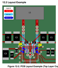
    Regarding 2, please follow the datasheet layout example below:

    The PMID and SYS 0.1uF caps are most critical and require the SWx pins to via to the inductor.  The inductor can be as shown above or directly under the IC on the bottom layer.

    Regards,

    Jeff