LM74900-Q1: How to calculate gate drive current for MOSFET

Part Number: LM74900-Q1
Other Parts Discussed in Thread: LM74700-Q1, LM74722-Q1, LM74910-Q1

Tool/software:

Hi Team,

My customer would like to parallel three FETs to support 100A application.

May I learn from you how to know driving capability for FET?

Customer use PSMN2R3-100SSE*3 for 8~48Vin/100A, besides FET at on status, I also worry about turn on/off.

BTW, I have check excel sheet and driving current from datasheet. But would like to learn more from you.

Regards,

Ben

  • Hi Ben,

    BACKGROUND:


    Ideal diode controllers are capable of driving multiple parallel FETs on a single GATE driver pin for high current applications and better thermal performance.

    With increase in number of parallel FETs, it is important to know the impact on the design since it has its own limitations.


    LIMITATIONS:


    STARTUP TIME:


    First, FET turn on and off time is increased.

    Considering the constant Gate source current and sink current of an Ideal Diode controller. As the number of FETs in parallel increases the turn ON and turn OFF time of the FETs increases due to increase in total gate capacitance.

    Approximate calculation can be done as shown:

    For Turn ON time calculation,  Ton = (Total Ciss) x 5V / peak source current

    For Turn OFF time calculation,  Toff = (Total Ciss) x 5V / peak sink current

    N x FETs will have a total Ciss of N x Ciss (individual)


    As an example, Let us consider DMTH43M8LFG as the FET and LM74700-Q1 as the FET controller.


    DMTH43M8LFG


    LM74700-Q1


    4x DMTH43M8LFG FETs have a total Ciss of 4 x 2.798 nF = 11.2 nF

    So, the Ton time = (11.2nF) x 5V / 11mA = 5.09 us

    and Toff = (11.2nF ) x 5V / 2.3A= 24.3 ns


    Next,

    VCAP needs to be scaled with increase in Ciss.


    VCAP needs its own time to charge and reach its UVLO (6.6V typ.)

    This will add another time to startup.


    For controllers with back-to-back FET driving capability, same implies to FETs controlled by HGATE also. HGATEs have low charging current on purpose to control the inrush current. By paralleling the FETs turn on time will increase further. Also, it is recommended to use a resistor in series with each FET gate of around 5-10ohms to dampen the oscillations (if any) due to FET parasitic.


    Next, for controllers that support reverse current blocking, AC super imposed rectification performance is affected.


    The maximum AC super imposed signal that an Ideal Diode can rectify depends on then FET used and the charge pump current strength. For more understanding on this please refer to the Application Report.

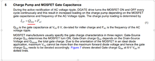
    Here, Qgm will increase proportional to the increase in number of FETs and hence maximum frequency that can be rectified will decrease.  

    As an example,

    LM74700-Q1 with 1xDMTH43M8LFG can rectify up to 25KHz whereas with 4x DMTH43M8LFG FETs can rectify up to 6KHz. 

    CONCLUSION:

    Ideal diode controllers can operate multiple MOSFETS in parallel by making sure charge pump capacitor used, follows the specified condition.


    Selecting higher number of FETs is important for high current designs but some trade-offs have to be made as explained earlier.

    If faster turn on or higher frequency AC signal has to be rectified, one can choose controllers with higher charge pump strength like

    LM74722-Q1,LM74810-Q1,LM74910-Q1.

  • Thanks for the detail explanation Slight smile