This thread has been locked.

If you have a related question, please click the "Ask a related question" button in the top right corner. The newly created question will be automatically linked to this question.

UC2844: shutdown technique

Part Number: UC2844

Tool/software:

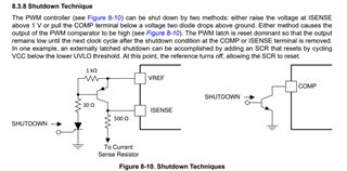
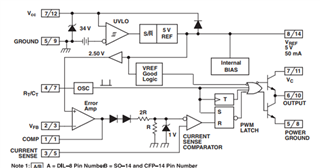
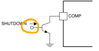
I'm looking to implement the shutdown technique using UC2844.

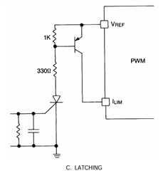
I want to implement a latch using an external circuit, but the datasheet doesn't provide much information, making it difficult to implement.

I'm curious about the criteria for selecting each resistor and the operating principle.

Thank you.


  • The pictures above are the shutdown materials I mentioned.

  • The shutdown techniques you've shown are to shutdown the PWM output while the controller remains fully biased (VREF still regulating). The two methods for achieving this are to either pull the CS HIGH, above the 1V threshold or pull the COMP, LOW to GND.

    Which method is better depends what signal you have available to trigger the shutdown operation. The CS method shown is more complex and involves an SCR. The resistors are chosen to give the minimum amount of holding current required to maintain the SCR in a latched state (details would be shown in the SCR data sheet). I prefer the COMP method and maybe even consider a simple logic level MOSFET as the pull down device.

    Steve

  • Thank you for your helpful response.

    I understand the shutdown condition from your answer.

    Now, I want to use the method shown in the picture above. How should I apply or connect the shutdown signal marked with a yellow circle in the picture?

    I'm not sure where exactly to connect it, and I have a lot of difficulty understanding how to implement this.

  • Use a logic level, N-channel MOSFET that is rated for VDS>10V, VGS=5V. The MOSFET is not switching, only active when you want to shutdown the controller. When you desire to shutdown the controller, you apply 5V (or 3.3V) shutdown signal to the MOSFET VGS. The shutdown signal might come from a μC, or any digital logic. This is a very simple circuit to design and you decide/assign what are the conditions when you want to shut down.

    Regards,

    Steve

  • Thank you for your helpful response.

    Does digital logic mean that I need to design a separate circuit so that 5V voltage is applied in case of overcurrent?

    I'm in a situation where I can only configure circuits using analog components.

  • Digital or analog, however you can apply +5V to the gate of the MOSFET, to short COMP to GND.