TPSM33615: Missing information into the drawing RDN0011A

Part Number: TPSM33615

Tool/software:

Hello,

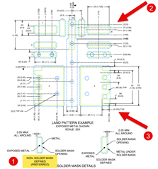
First, on page 2 of RDN0011A, I don't see the dimensions of the copper pads. They seems to be drawn in gray but no quotes.
The pads quoted are in green witch it should be the solder mask opening.

www.ti.com/.../mpqf642a.pdf

Into the datasheet of the TPSM33615, on page 40, we can see the recommended layout. As a designer, I have trouble to follow
this example because I doubt of that your team spend a lot of time an effort on it. Why?, the PAD #6 is obviously wrong. The design
files of the evaluation board has not routed nets. (BSR236A)

As a designer, we have to choose between IPC recommendations for a package and the manufacturer recommended package.
Must of the time, I follow the IPC standard before the manufacturer recommendations. I use the manufacturer recommendations 
when the package is odd and when I trust the manufacturer did a lot of soldering tests with the package. By the quality of what I
see, I am not confident that TI took it seriously enough.

To use it, I would need an updated drawing with a confirmation that you did enough soldering test.  

https://www.ti.com/lit/ds/symlink/tpsm33615.pdf

Best regards

  • Hello,

    This device is a module with an inductor attached inside of the package. Since the output inductor is inside the package, a connection to the SW node (Pin 6) is not needed.  However, as shown in the example layout on page 40 of the datasheet, it could be used as a test point to probe the SW node voltage. The boot capacitor is also inside the package, which is why the BOOT pin (Pin 7) is also left unconnected

    For proper connections in schematic and layout, please refer to the information in Section 8 of the datasheet.

    I will reach out to the team regarding your questions about the package drawing.

    Best regards,

    Ridge

  • Hello,

    Since we have not head back in a while, I will be closing this thread. If you have more questions, please open a new thread. 

    Best regards,

    Ridge

  • Hello,

    You gave an answer about the unconnected pin but you never have answered about the package drawing, the footprint recommendations and how much test have you done with the package. The team you have reach has never answered back.

    Best regards,

    Fred

  • It looks like the team has updated the drawing but there still have some inconstancies.

    1. Non soldermask defined PAD is preferred but all the pads seams like they are Solder Mask Defined.

    2.There is no quote for the blue line of the pads, we can estimate them by using the 0.05 opening.

    3. There is no quote on the pad 4 & 5.

    Again, what I doesn't like the most about all the small details that is missing, it's the fact that it is hard
    to have confidence that all the proper effort was made to make sure this pattern would lead to an easy 
    and repeatable production process.

    Fred

  • Hello,

    I am still waiting for comment from the team and will update you when they reply.

    Best regards,

    Ridge

  • Hello Ridge Lahti, do you have any answer for this thread?

    thank you,

  • Hello,

    Please see the below answers numbered to correspond with the questions:

    1. Non soldermask defined PAD is preferred but all the pads seams like they are Solder Mask Defined.

    All of the shown drawings are solder mask defined. The team will update the drawing accordingly, regarding the NSMD comment.

    2.There is no quote for the blue line of the pads, we can estimate them by using the 0.05 opening.

    Yes. The solder mask details show the solder mask offset as 0.05mm for this package.

    3. There is no quote on the pad 4 & 5.

    Pad 4 & 5 have the dimension, the metal under mask offset is 0.05mm (larger) from the edge of the solder mask opening.

     Best regards,

    Ridge