UCC21710: Selection of proper Current threshold limits of OC operation

Part Number: UCC21710

Tool/software:

Hello Experts,

We are designing the OC threshold limits and a little confused as to that limits we are allowed to set.

Firstly the SiC module we are using is the MSCSM120HM16CTBL3NG

Looking at the datasheet, the Rds(on) ranges from 12.5mohm to 16mohm

They also mention the Rds(on) vs the junction temperature curve(Tj)

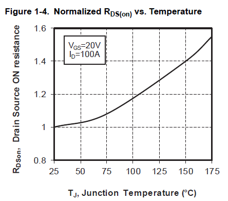
we are a little confused as to what Rds(on) value do we take for OC calculation

Secondly we would like to allow as much current as possible, the before the OC is triggered., Looking at the SiC data sheet:

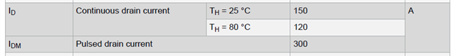
So is it okay to design the OC so trigger at 300 amps, or should OC trigger at 120 or 150 Amps?

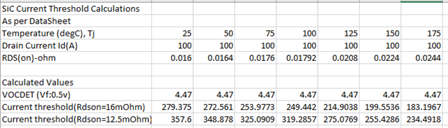
This is what we have so far, and would like to hear your thoughts on the safe limits of OC:

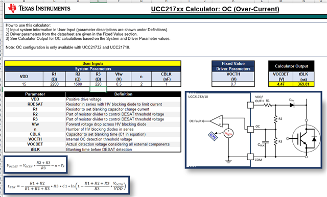
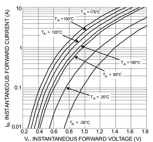
The high voltage diode used is the US3M-13, looking at its Ir vs Vf curve we see that the Vf will be approx 0.5v, if R1 is 2.2K (20v/2.2k = 9mA)

I calculated the current thresholds if the typical value of Rds(on) is 1`6m ohm and 12.5 mOhm, w.r.t the Rds(on) vs Tj curve posted above, If we consider the Rds(on) to be 12.5 mohm the threshold crosses 300 Amps !!, Is my understanding correct?

Thirdly, the OC circuit shown in the calculator tool, is primarily dependent on the the HV diodes, if the HV diode fails , the high voltage is going to be passed on to R2 which can lead to failure of UCC? Also capacitive coupling across the diode will bring high voltages to the top of R2, and also possibly into the IC. How are these points taken care in the OC design using UCC21710?

  • Hi Ak,

    Thanks for the detailed question.

    The max current allowed by the power module changes at different temp (150A at room) and (120A at hot). this is the maximum operating current of the Power Module (PM) and it should not be violated for normal operations (based on system temp). However it can withstand 2x its max current (pulse current) only for short time during SC event. 

    so the normal operating current has to be ~the max current supported by the Power Module (PM) shouldn't exceed.   You can reach out to the manufacturer for the SC withstand time. So that way, you can define how much duration is allowed during a SC event for the worst case scenario.

    From gate driver, you need to define the voltage divider ratio, so that the Voc threshold is reached + gate is turned off  before the SC with stand time is reached. If you plan the worst case scenario (Room and Hot) -> whichever has the lowest SC time, plan for it, the other conditions will be automatically covered.

    Yes, when HV diode fails it  will expose HV to gate driver, its generally recommended to plan 2 HV diodes in series, so that the HV diode withstand voltage can be half and can withstand higher system voltage. 

    We recommend to plan low capacitive HV diode for this purpose, so that OC/DESAT node is not pulled low. You could also use Schottky diode on the OC/DESAT node, so that the OC/DESAT node is not pulled lower.  Please refer our reference schematic diagram below,

    https://e2e.ti.com/support/power-management-group/power-management/f/power-management-forum/1377445/faq-ucc21710-q1-schematic-and-layout-recommendation

    Hope it answers your question.

    Thanks

    Sasi

  • Hi Sasi,

    Thanks for the reply, Could you recomend a starting HV diode part number/series so that we can know the detailed charectaristics of the diode needed for this application, the link provided does not give this information.

  • Hi Ak,

    We have used STTH112A HV diode. You can look for HV diodes with lower capacitance for the system voltage requirement.

    Thanks

    Sasi