- Ask a related questionWhat is a related question?A related question is a question created from another question. When the related question is created, it will be automatically linked to the original question.
This thread has been locked.
If you have a related question, please click the "Ask a related question" button in the top right corner. The newly created question will be automatically linked to this question.
Tool/software:
Hi,
I'm working on a hotplate project using an ESP32. The hotplate has two power inputs: a USB-C port providing 5V for programming, and a DC jack for 12-30V to power the entire circuit and the hotplate. When powered through the USB-C port, everything functions correctly with sufficient current. However, when using the DC jack with a 24V 6A supply (or any voltage above 12V), the circuit seems to drop the voltage correctly to 5V and then to 3.3V, but the current appears insufficient, causing the ESP32 and other ICs not to power on. Notably, when both the USB-C port and the DC jack are used together, everything works perfectly.
I used the reference design from the TI Webench tool for the LMR50410XFDBVR to drop the voltage from 24V to 5V, and then an AMS1117-3.3 to step down to 3.3V. Given that the LMR50410XFDBVR circuit follows a proven reference design, I suspect the issue might lie elsewhere in the circuit. For reference, here's the link: webench.ti.com/.../1
Does anyone have any insights into what might be causing this problem? I’ve attached pictures and PDFs of my schematics for reference. If you need any more information or tests from my side, please let me know. Any advice or suggestions would be greatly appreciated. (P.S. I'm 15 years old, so any additional troubleshooting tips or insights would be really helpful.)
Hi Loic,
I think you're right that there isn't an issue with the LMR50410 schematic. Make sure you're following any layout guidelines available in the data sheet and EVM users guide available to view online here under "technical documentation":
https://www.ti.com/product/LMR50410
You may want to look at your power delivery circuit for the DC jack. Make sure there are no other components in the circuit overloaded when 24V is applied compared to the nominal 12V from USB-C.
Best,
Ryan
Hi, I found that the issue was due to an auto-reset pin not receiving enough power. However, I now have a more critical problem: the LMR50410 keeps blowing up. This has happened on five PCBs so far. The chip fails immediately upon plugging in the power supply (it happens during or right after plugging it in, not after being connected for some time). Also, I was powering it the circuit with 24v 6A. Despite this, the rest of the circuit works perfectly when powered via USB-C after the chip has blown. Any ideas on what might be causing this?
Hi Loic,
Apologies for the delay. I can take this thread from here.
Can you please give more context to your situation? Please provide the following:
Thank you,
Joshua Austria
Hi,
For the setup, I’m using the exact circuit as shown in the attached pictures on the PCB.
The max input voltage is 30V and the max output current is undetermined (It's an aluminium PCB hotplate and can use as much current as it's given). The inductor has a saturation current of approximately 5.3A (which make me think that I should really change it because it may be or will become a problem because I (want to) input up to 10A). All the input capacitors are rated at 50V.
Also, I’ve noticed that the issue seems to occur primarily when the power supply is plugged into the power outlet before being connected to the circuit.
Here’s the layout for your reference (Only the main board; Heating pcb is separate):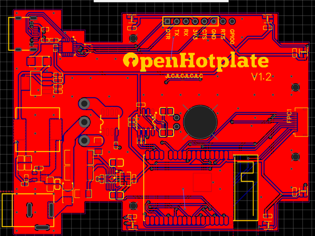
Hi Loic,
Apologies for the confusion. I meant what is the current draw to be expected from the output of the LMR50410 specifically? This is a 1 A part and is not designed to supply more than 1 A itself. Please see section 7.3 of the datasheet below:

Going above this limit will employ the part's overcurrent protection at which point the device will no longer supply power. Please see section 8.3.6 of the datasheet for more on this. You may need to use a higher current part for your application.
Thank you,
Joshua Austria
Hi, The current draw to be expected from the output of the LMR50410 is 376.75 mA (as shown in the schematic on top).
Hi Loic,
Understood. From a schematic and layout perspective, the only thing I can see potentially as an issue with your application is that the SW node is relatively long.
However, this is not to say that the device is not being subjected to any sort of inadvertent over-stress. Can you try and connect your power supply directly to the input trace of the device and isolating the LMR50410 from all upstream and downstream components? I want to ensure that this is not a systemic issue, i.e. something in your application that is causing voltage overstress on the device.
Do you mind also sending the power supply specs you are using to power the system? Also if you can please send pictures of the failed devices, it may be helpful to understand from what point and how the device is failing. You can take a look at this Pin FMA which details circuit conditions that can cause device damage other than going above the abs max table ratings in the datasheet.
Thank you,
Joshua Austria
Hi,
I am not experienced to know how to test the LMR50410 while it being isolated, but I am almost sure it is not a problem with the other components (esp32 and etc) as it worked and still works perfectly with the USB-C port. The model of my power supply is CJ-2460 ans is a DC 24V 6A power supply. I included the picture of three of the LMR50410 that exploded.
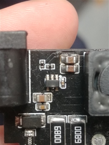
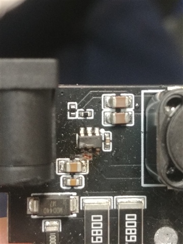
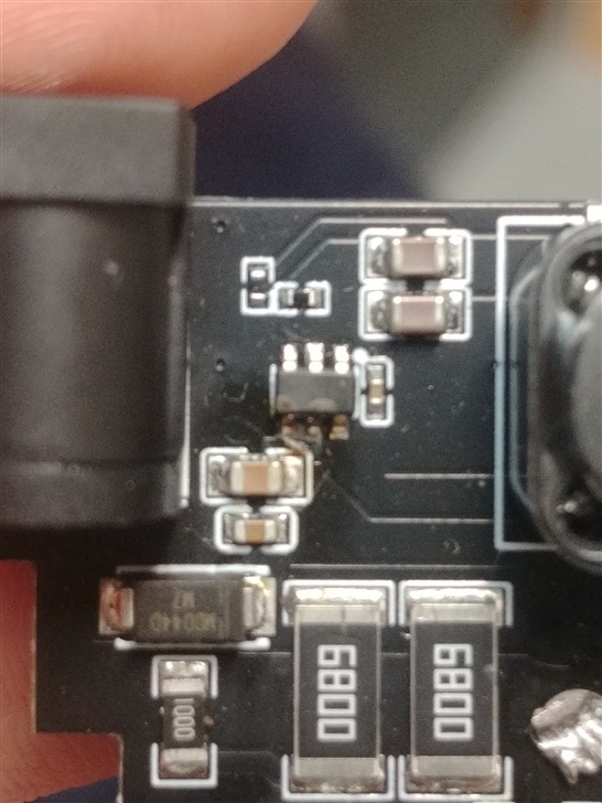
Hi Loic,
Thanks for sending that. It looks to be a consistent issue at input which we usually see when the abs max rating of the VIN pin is violated. Can you do the following:
Thank you,
Joshua Austria
Hi,
I do have access to an oscilloscope, but I don't have a "tip and barrel" probe, and I'm not entirely familiar with how to use it effectively yet. That said, I suspect the issue might be related to inrush current. This would explain the behavior I'm seeing. Additionally, when I plug in the DC jack, there's noticeable sparking, which I've read can cause brief high-voltage spikes that could potentially damage sensitive components.
I've attached a picture of the bottom layer of my layout for reference.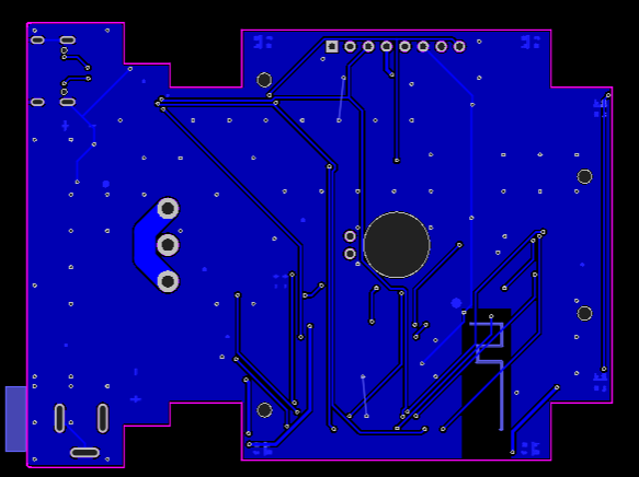
Hi Loic,
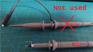
The tip and barrel probe is created by removing the GND wire and tip of your probe to expose its "barrel GND." You then wrap a thin wire around the barrel and use the tip to probe your signal while connecting the wrapped wire to GND. This picture below shows identical probes, one with the default probe and alligator clips, and the other with these two elements removed and replaced with the wrapped wire:
In any case, if you are not comfortable with this, I would advise just using the normal probe leads to take the waveforms listed before. I am also suspecting that this is an issue with the DC power jack. If we see voltage spikes on the device input when hot plugging in the jack, we will have found the issue and can find some ways to curb these spikes such as adding an electrolytic capacitor on input.
Thank you,
Joshua Austria
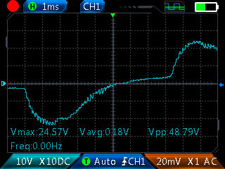
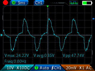
Hi, I was able to get some results. I only took the ones which the vpp was higher than normal (ex: 50v with a 24v psu) and it did not always happen. Included are some screenshot. Let me know if you think I did anything wrong when taking the measurement.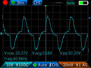
Hi Loic,
Just to confirm was this scope shot taken with the IC desoldererd?
If this is the input voltage going into the device, it would make sense that the device is blowing at input, as negative voltages are being put onto the input pin of the device. Here are the absolute max ratings from the datasheet. Voltages that exceed these limits can damage the device:
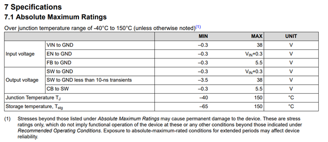
It seems like you may need to find a different protection circuit to ensure that the voltages that enter the VIN pin from the dc power jack are within these limits.
Thank you,
Joshua Austria
Hi,
Yes this scope shot was taken with the IC desoldererd.
Also, what protection circuit would you recommend in my case?
Thanks,
Loic
Hi Loic,
Before using a protection circuit, I would recommend looking through your dc power jack's datasheet and make sure that it is being used appropriately and is outputting voltage as expected. This type of power jack may be inappropriate for this use case as it looks like there is significant under/overshoot on VIN.
In terms of a protection circuit, this is usually out of Ti's wheelhouse for recommendations, but there are plenty of sources online for input voltage protection circuits. I will say that you need something to make sure the voltage that enters the IC input is limited to the range of -0.3 V to +38 V. The simplest way to do this would probably be a half wave rectifier using a diode, but you might want to experiment with other power sources/ways to power your device that can provide a stable input voltage.
In any case, I will close this thread for now. Should you need further help, please don't hesitate to reach out again.
Thank you,
Joshua Austria