This thread has been locked.

If you have a related question, please click the "Ask a related question" button in the top right corner. The newly created question will be automatically linked to this question.

UCC2818A-Q1: Voltage Error Amplifier

Part Number: UCC2818A-Q1
Other Parts Discussed in Thread: UC3854

Tool/software:

Hi Team,

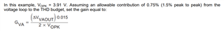
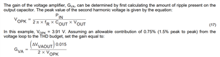
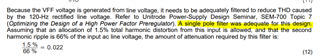
Please tell me the gain of the voltage error amplifier shown in the typical application of UCC2818A-Q1 datasheet and what is the output of the voltage error amplifier during light load conditions such as 35W and full load power such as 250W.

Best Regards,

Aravind S.

  • Hello Aravind, 

    In the example shown, Gva is the closed-loop gain of the voltage error-amplifier at the frequency of the PFC output ripple voltage. 
    That ripple voltage is indicated as 3.91V zero-to-peak, and that ripple frequency is twice the AC line frequency.

    In the section preceding the Gva discussion, it was shown (by SEM-700 Topic 7) that allocating1.5% of the VFF ripple contributes to half of 3% THDi from the 3rd harmonic of the line.  Similarly, 1.5% of the VA output ripple contributes the other half.  So the EA gain necessary to attenuate this ripple (divided down from Vout) is: 

    1.5% of VAout(max) (= 5V) /  (2*3.91V) =  0.0096 = Gva at 100Hz (or 120Hz) 
    This value of Gva is used in the follow-on equation to calculate Cf. 

    Since the UCC2818A-Q1 has a voltage feedforward function, VAOUT is not influenced by input voltage, so its amplitude is basically proportional to output power. 
    If 5V corresponds to maximum power (250W), then VAOUT = (35W/250W)*5V = 0.7V corresponds to 35W (14% of full load). 
    VAOUT voltage for other loading is estimated the same way. 

    Regards,
    Ulrich

  • Hi Ulrich,

    Can you please explain how the output power is directly proportional to the voltage error amplifier output? Please explain with some examples.

    Regards,

    Aravind S.

  • Hi Ulrich,

    In my application, the supply frequency will vary from 350Hz to 800Hz. However, performance should not deviate within this range. So, I should consider 800Hz for my calculations, right?

  • Hello Aravind, 

    To better understand the UCC2818A-Q1 error-amplifier relationship to output power (and by extension, to input power) please review this application note concerning the UC3854, particularly around page 3-281.  https://www.ti.com/lit/pdf/slua144 
    It is written for an older PFC controller, but its operating principles form the basis for the UCC2818A-Q1, and the app-note discussion on multiplier operation (including the error-amp) still applies.  

    For variable input frequency operation, it is best to design for 800Hz.  Strictly speaking, it is impossible to ensure that "performance should not deviate" between 350Hz and 800Hz; it will deviate.  However, you can expect that performance should be better at 350Hz, so 800Hz is the correct design target.

    Regards,
    Ulrich

  • Hi Ulrich,

    Thanks for your above comments.

    Here a single pole filter was adequate is mentioned for this design. But according to my design the fundamental frequency is varying is 350Hz to 800Hz. Is single pole filter is sufficient for this design or not. Please explain.

    Regards,

    Aravind S.

  • Hi Aravind, 

    The decision that a single-pole filter was adequate for a 50Hz design was made by the author of the design example.  A two-pole filter can have lower ripple voltage but is more complicated to design (see design guides for UC3854 controller https://www.ti.com/lit/pdf/slua144 pages 3-284, 3-285). 

    The assessment of adequacy depends on how much ripple attenuation you think you might require to meet THDi targets.
    But a filter good for 50Hz is also good for 60Hz.  

    Similarly, a 1- (or 2-) pole filter on VFF for 350Hz will be good for all higher frequencies, certainly to 800Hz. 

    Regards,
    Ulrich

  • Hi Ulrich,

    According to my requirement, the power factor should be greater than 0.98 and THD should be less than 1.25% for all frequencies that vary from 350Hz to 800Hz.

    Can you explain to me which value I have to consider for ripple frequency so that I can achieve both the power factor and THD in light load and full load applications?

    Regards,

    Aravind S.

  • Hi Aravind, 

    The requirement for <1.25% THDi over a light to full load range is extremely stringent.  I don't know if it is even possible. I suppose it could be possible if enough technology is designed in to overcome the sources of distortion, but I think it will be very complex and very costly and time consuming.  
    I will not be able to help you achieve this goal. 

    PF is a combination of phase-shift and harmonic content of the input current with respect to that of the input voltage. 
    Please see this paper on the topic:  4812.PF_THD_Power.pdf

    Most of the phase shift comes from reactive current in the line-filter X-caps, the magnitude of which depends on their total impedance at the input frequency. 
    The harmonic content comes from distortions introduced by the controller, mostly from ripple voltage on the error amp output and ripple on the VFF node.
    Those two signals are inputs to the multiplier whose output forms the reference signal for shaping the input current.   
    The design guide that I referenced previously discusses how to minimize them, although the paper considered 3%THDi to be adequate. 
    You will need to modify the design targets so that they both contribute < 1% THD combined, in my estimation.  

    The remaining THD comes from current-sense offsets, propagation delays, and other factors which I have no experience about.  
    I have reached the limit of my ability to help you. 

    Regards,
    Ulrich

  • Hi Ulrich,

    Thanks for your reply.

    In the calculation of feedforward and Vcomp, the ripple frequency needs to be considered. Which value should I use for my design to achieve the best results in my frequency range from 350Hz to 800Hz? If I select the higher frequency, say 800Hz, how will it attenuate the harmonic content in the lower frequency, say 350Hz?

    Regards,

    Aravind S.

  • Hi Aravind, 

    For the VFF ripple attenuation to minimize distortion, you should design for 350Hz, which will also work for 800Hz as I mentioned earlier.  

    When I said " it is best to design for 800Hz. " two days ago, I meant in reference to the error-amp gain needed to attenuate error-amp output ripple.
    Also, the choice of switching frequency should be based on the 800Hz end of the operating range. 

    It is apparent that different aspects of the PFC design require optimization at different ends of the input frequency range. 
    I apologize for making that blanket statement without qualifying under which conditions it applies.   

    In general, all corners of a design (high line, low line, high load, low load, high freq, low freq, high temperature, low temp, etc., etc.) must be considered while trying to meet all of your design requirements. 

    Regards,
    Ulrich

  • Hi Ulrich,

    Based on your previous comments, I calculated the feedforward compensation network for 350Hz (fundamental) and considered 1.25% as THD.

    So fp = 0.0189*700(2nd order of 350) = 13.23Hz.

    The calculated Rff = 15.367kohms.

    so the calculated Cvff = 783nF.

    With the above RC values, I plotted a Bode graph and attached it below for your reference. The circuit schematic is also attached. Please let me know if using these values in my application will achieve a THD% of 1.25 to 1.5 for the input frequency range from 350Hz to 800Hz.

    Frequency Magnitude Phase
    14.2 -3dB -46°
    350 -28dB -87°
    500 -31dB -88.4°
    750 -34dB -88.9°
    1000 -37dB -89.24°
    1200 -38.7dB -89.33°
    1600 -41.62dB -89.52°

  • Hello Aravind, 

    Your calculation for Rff and Cff should follow the design method in the UCC2818A-Q1 datasheet.  I'm not sure how design a 2-pole VFF filter on this device.

    Your simulation is of a voltage source driving a series R-C filter.  It is not valid for UCC2818A-Q1.
    The actual VFF circuit in this device is a current source driving a parallel R-C filter.   Please read the datasheet on this topic. 

    The VFF circuit contributes only about half of the total THDi.  The ripple on the error amplifier output (VAOUT) contributes about another half.  The remaining THD comes from offsets and other non-linearities in the system.     

    In any case, I cannot predict or guarantee any specific amount of real-world THDi from a simulation model.  No model is detailed enough to include every possible non-linearity that may occur in a circuit.  You simply have to build a prototype and measure it. 
    The simulation can give you a gross idea of the 3rd harmonic THD based on the ripples on VAOUT and VFF.  This may be most of it (THD), but not all of it.  

    Regards,
    Ulrich