This thread has been locked.

If you have a related question, please click the "Ask a related question" button in the top right corner. The newly created question will be automatically linked to this question.

LM5176: Regarding the gate signals (HDRV1, LDRV1) and bootstrap operation during boost operation.

Part Number: LM5176

Tool/software:

Hello. We are currently examining the circuit while utilizing your evaluation board (LM5176EVM-HP).

I need some additional information LM5176 that are not specified in datasheet: 

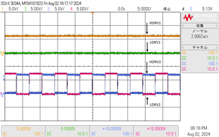
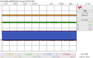
During boost operation, HDRV1 is fixed high and LDRV1 is fixed low.

How does the LM5176 charge the bootstrap during boost operation?

We understand that LDRV1 must be switched in order to charge the bootstrap.

 The image below shows each gate signal during boost operation.

Best regards,

Takano

  • Hi Takano,

    thank you for using the E2E forum.

    The LM5176 is observing the voltage on the boot cap (BOOTx). In case the voltage goes under the threshold voltage due to the leakage current it will do an recharge cycle and put SWx low for a short pulse.

    Best regards,

     Stefan

  • Hi Stefan,

    Please tell me how the gate signal works when a charging cycle is performed.

    Our understanding of the gate signal works when a charging cycle is performed is as follows. (Take boost operation as an example.)

    The boot cap (BOOT1) voltage falls below the threshold voltage.

                               ↓
    LDRV1 goes high and HDRV1 goes low.
                               ↓
    SW1 goes low.
                               ↓
    Charging to the boot cap is completed.
                               ↓
    LDRV1 goes low and HDRV1 goes high.

    Best regards,

    Takano

  • Hi Takano,

    let me double check on that - I will come back till end of this week.

    Best regards,

     Stefan

  • Hi Takano,

    i need to revise my initial comment. The LM5176 has in internal charge charging circuit which recharges the Boot Cap on the non switching  switch node from switching side.

    Best regards,

     Stefan

  • Hi Stefan,

    What is the charging operation for each BOOTx during boost operation?

    Our understanding is as follows.
    BOOT1: Charged from the internal charging circuit of the LM5176.
    BOOT2: Charged by the switching operation of LDRV2.

    Best regards,

    Takano

  • Hi Takano,

    yes, your understanding is right.

    And vice versa for BUCK operation

    BOOT1: Charged by the switching operation of LDRV1   (or in more detail SW1).
    BOOT2: Charged from the internal charging circuit of the LM5176.


    Best regards,

     Stefan